
Method and system for data rate optimization in a digital communication system

Inactive Publication Date: 2007-03-06
MACOM TECH SOLUTIONS HLDG INC
View PDF3 Cites 32 Cited by
  • Summary
  • Abstract
  • Description
  • Claims
  • Application Information

AI Technical Summary

Benefits of technology

[0014]As advantages over prior art, the method and apparatus disclosed herein allows an optimal symbol rate and optimal constellation size to be determined and utilized during a communication session. Other settings may also be optimized through the training process. These optimal settings may be selected to maximize the signal to noise ratio, minimize signal transmit power, maximize bit transfer rate, reduce echo or crosstalk, minimize bit error rate, simplify implementation complexity, or any other aspect of system operation. Through use of these optimal settings, communication system operation is improved or enabled.
[0016]Yet another advantage of the method and apparatus described herein is it in one embodiment the constellation size and symbol rate may be set by with guidance from a technician or to follow certain guidelines. This allows other than the optimal settings to be utilized but with emphasis with other parameters. Hence it is contemplated that a technician may control or limit one or more operational parameters of the communication device to achieve desired operation. For example, the frequency of operation may be reduced, to prevent or reduce crosstalk yet all other parameters, such as transmit power and constellation size optimized. It is contemplated that any variable discussed herein may be controlled while one or more other parameters are optimized.
[0021]In one aspect of the present invention, a maximum bit rate is achieved utilizing an optimal symbol rate and constellation size without significant penalties in power.

Problems solved by technology

Prior art systems select and fix the symbol rate or constellation size at the time of design suffer from being limited to a predetermined particular setting when other settings may be preferable.

Method used


Image

  • Method and system for data rate optimization in a digital communication system
  • Method and system for data rate optimization in a digital communication system
  • Method and system for data rate optimization in a digital communication system

Examples


Embodiment Construction

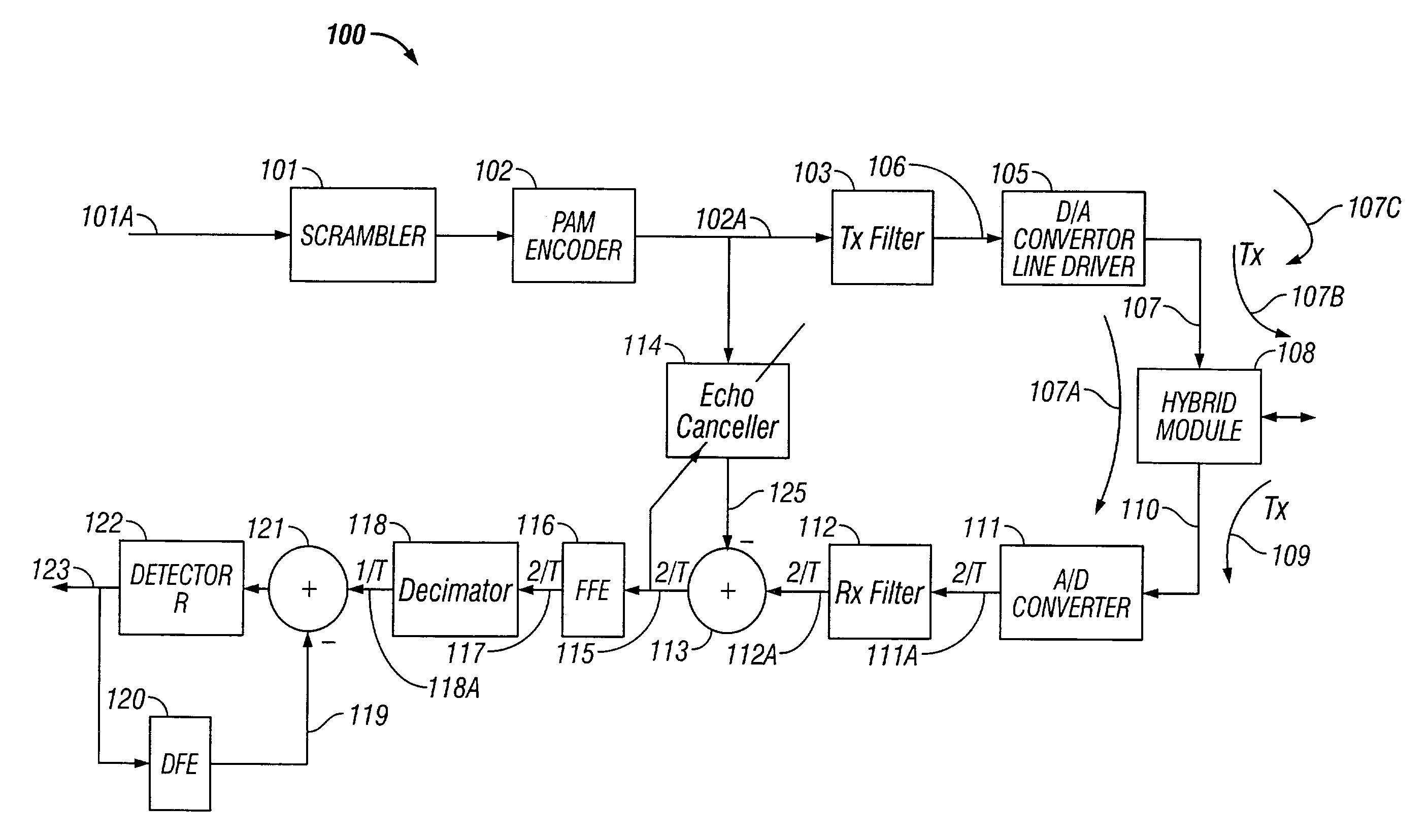
[0039]Definitions: The following definitions are used in various aspects of the present invention and with respect to digital communication systems (but not exclusively):

[0040]“Δfsym”: Symbol rate increment;

[0041]“fsym,k”: Symbol rate for the kth allowable symbol rate;

[0042]“PSD”: Power spectral density;

[0043]“BER”: Bit Error Rate;

[0044]“DFE”: Decision Feedback Equalizer;

[0045]“Ek(f)”: Residual echo power spectral density for the kth symbol rate;

[0046]“fsym-max”: Maximum symbol rate;

[0047]“FFE”: Fractionally Spaced Feed Forward Equalizer;

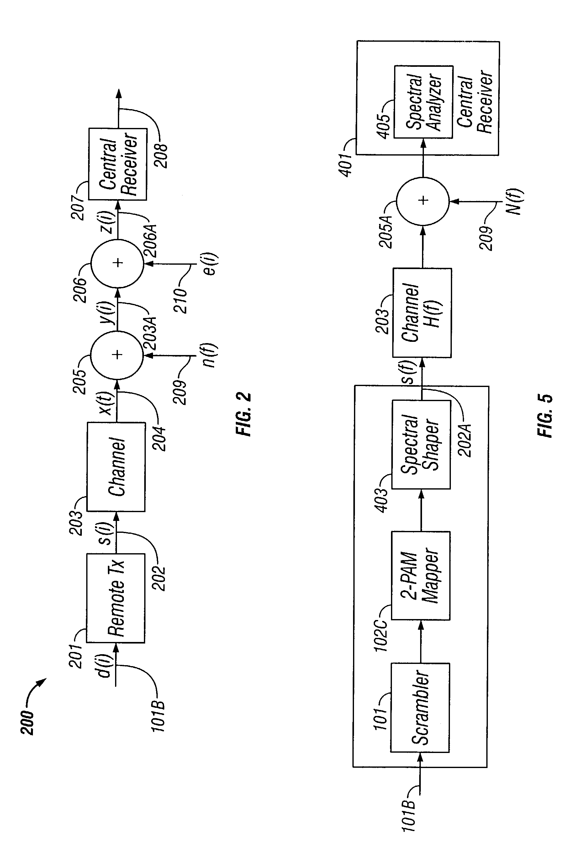
[0048]“H(f)”: Ideal loop gain function;

[0049]“M”: Constellation size;

[0050]“MSE DFE”: Mean Square Error Decision Feedback Equalizer;

[0051]“PAM”: Pulse Amplitude Modulation;

[0052]“N(f)”: Noise power spectral density;

[0053]“R”: Data rate ((No of bits / symbol)*symbol rate);

[0054]“STU-C”: Transceiver unit at central office;

[0055]“STU-R”: Transceiver unit at remote office;

[0056]“Sk(f)”: Nominal front end transmit signal PSD for the kth symbol rate;

[0057]“...


PUM


Abstract

A method and for optimizing bit rate throughput in a digital communication system is provided. The method includes establishing a relationship between signal to noise ratio and plural symbol rates for a particular constellation size. The method also includes determining noise power spectral density (N(f)), wherein N(f) is determined during a silent period of line probing; determining Xk(f), wherein Xk(f) is determined by turning on a remote station transmit signal, after N(f) has been measured and determining residual echo Ek(f), wherein Ek(f) is determined by turning on a central station echo canceller.

Description

BACKGROUND OF THE INVENTION[0001]1. Field of the Invention[0002]The present invention relates to communication systems, and more particularly to data rate optimization in a communication system.[0003]2. Background[0004]Various technologies have been developed, such as Digital Subscriber Line (DSL) technology, to provide high data rates over ordinary twisted pair lines. Numerous various standards are currently used for transferring data over twisted pair lines.[0005]One such standard is V.90 (with a later version called V.92) published by the International Telecommunication Union (“ITU”), incorporated herein by reference in its entirety. The V.90 / V.92 standard defines the operation of a digital and analog modem for data transmission in a digital communication system. The V.90 / V.92 standard uses M-ary Pulse Amplitude Modulation (“PAM”) that samples signals at fixed intervals. Typically, a binary input stream is sub-divided into block of k bits called symbols and each symbol is represe...

Claims


Application Information

Patent Timeline
IPC IPC(8): H04L5/12H04B3/20H04B3/23H04B7/005H04L1/00
CPCH04B3/23H04L1/0003H04W52/26
Inventor ZHANG, XUMING
Owner MACOM TECH SOLUTIONS HLDG INC
Learn More