
Switching power supply integrated circuit

An integrated circuit, switching power supply technology, applied in the direction of high-efficiency power electronic conversion, electrical components, adjusting electrical variables, etc., to achieve the effect of low power consumption

Active Publication Date: 2011-12-21
BCD (SHANGHAI) MICRO ELECTRONICS LTD
View PDF4 Cites 34 Cited by
  • Summary
  • Abstract
  • Description
  • Claims
  • Application Information

AI Technical Summary

Problems solved by technology

However, how to achieve zero power consumption at light load or no load has become a major technical problem in the design of switching power supplies

Method used


Image

  • Switching power supply integrated circuit
  • Switching power supply integrated circuit
  • Switching power supply integrated circuit

Examples


Embodiment Construction

[0033] In order to make the above objects, features and advantages of the present invention more obvious and understandable, the technical solutions in the embodiments of the present invention will be clearly and completely described below in conjunction with the accompanying drawings in the embodiments of the present invention. Obviously, the described implementation Examples are only some embodiments of the present invention, not all embodiments. Based on the embodiments of the present invention, all other embodiments obtained by persons of ordinary skill in the art without making creative efforts belong to the protection scope of the present invention.

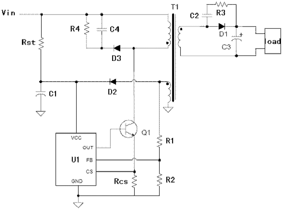
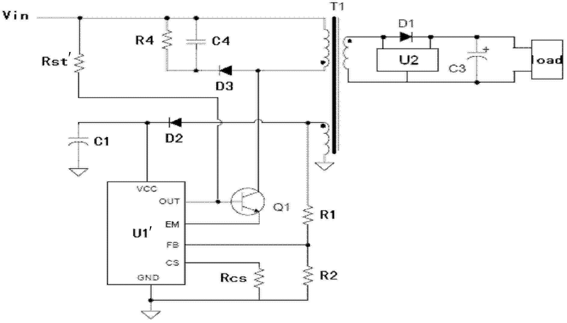
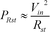
[0034] refer to figure 1 , figure 1 It is a common flyback control circuit in the prior art. Among them, U1 is the primary side controller. The input voltage Vin charges the power supply voltage VCC of the primary side controller U1 through the start-up resistor Rst. When the power supply voltage VCC of the primary side c...


PUM


Abstract

A switching mode power supply (SMPS) includes a power transistor coupled to the primary winding of transformer and a resistor coupled between the input power source and a control terminal of the power transistor for triggering a primary current flow through the power transistor for providing startup power. A primary side control circuit is configured to regulate the output of the SMPS. A secondary side control circuit is coupled to the secondary winding and being configured to provide a first electrical signal to the secondary winding when an output voltage of the SMPS is less than a first reference voltage, whereupon an awakening signal is induced in the auxiliary winding and causes the primary side control circuit to provide a turn-on signal to the power transistor. The primary side control circuit is configured to enter a standby mode or a normal operating mode in response to the awakening signal.

Description

technical field [0001] The invention relates to the field of integrated circuits, in particular to a switching power supply integrated circuit. Background technique [0002] Switching power supply is widely used in communication, control and other electronic systems as well as various household appliances and other electronic products due to its small size, light weight, and high power conversion efficiency. Generally, the energy consumption of electronic products usually has two modes: the running mode and the standby mode. With the popularization of various mobile phones and mobile consumer electronic products and the increasingly prominent energy problems, higher requirements are placed on the operating power consumption of switching power supplies. Moreover, today, the standby power consumption of various home appliances in society, homes, and offices has also become an important source of pollution. [0003] With the consensus on energy saving and environmental protec...

Claims


Application Information

Patent Timeline
Patent Type & Authority Applications(China)
IPC IPC(8): H02M3/335H02M1/36
CPCY02B70/16H02M3/33507H02M2001/0032H02M3/335Y02B70/10H02M1/0032
Inventor 郜小茹朱亚江陈超张美玲
Owner BCD (SHANGHAI) MICRO ELECTRONICS LTD
Learn More