Storage rack assembly for storing nuclear fuel elements

A technology for nuclear fuel elements and assemblies, which is applied in the fields of reactor fuel elements, nuclear engineering, nuclear power generation, etc., and can solve problems such as stimulation, high cost, and fuel element disposal problems.

A technology for nuclear fuel elements and assemblies, which is applied in the fields of reactor fuel elements, nuclear engineering, nuclear power generation, etc., and can solve problems such as stimulation, high cost, and fuel element disposal problems.

CN101615435AActive Publication Date: 2009-12-30CCI AG (CH)

Image

  • Storage rack assembly for storing nuclear fuel elements
  • Storage rack assembly for storing nuclear fuel elements
  • Storage rack assembly for storing nuclear fuel elements

Examples


Embodiment Construction

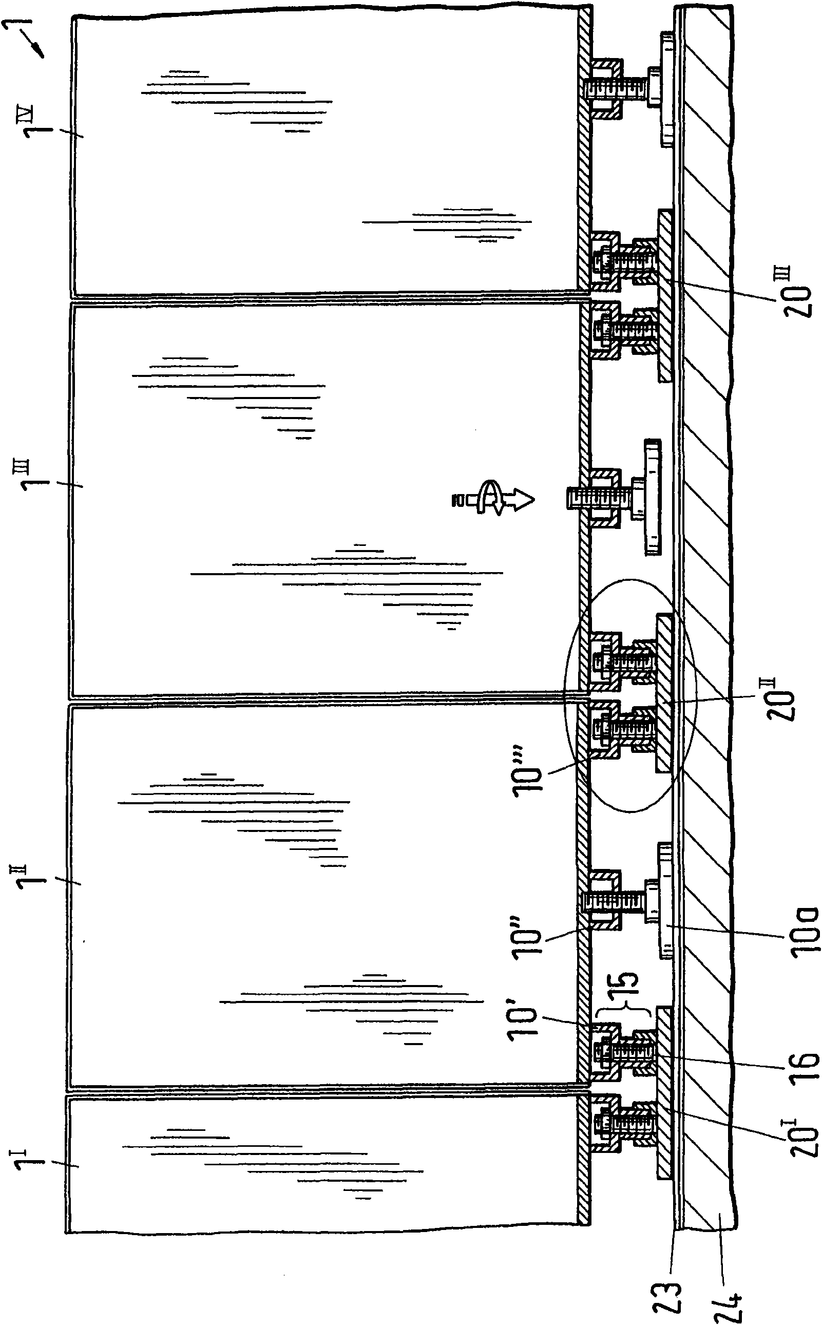
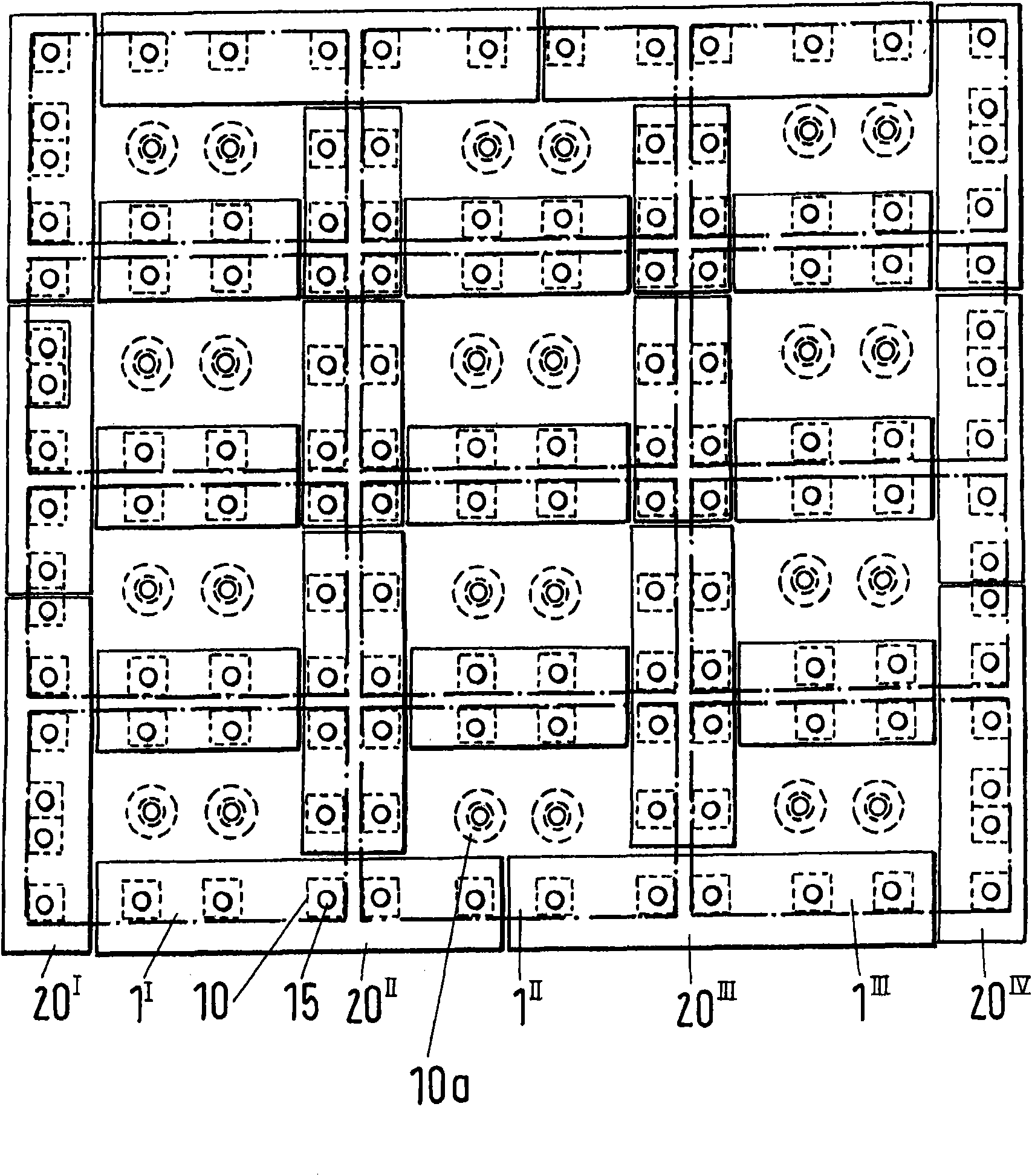
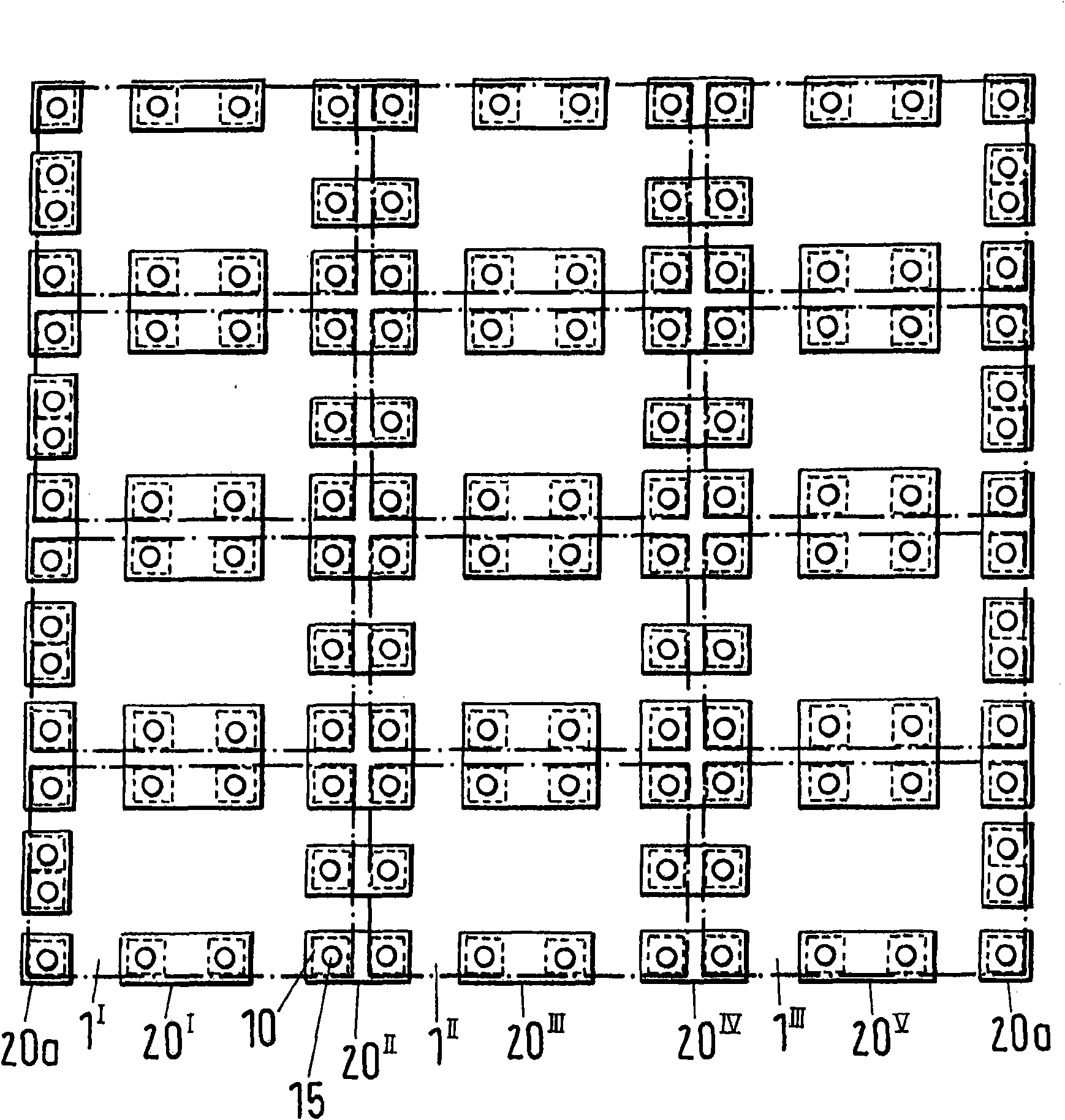
[0034] attached figure 1 The illustrated embodiment is a storage rack assembly for storing nuclear fuel elements in a storage pool, comprising at least two storage racks 1 I-IV , each comprising a plurality of vertically juxtaposed channels for receiving fuel elements. Furthermore, the storage rack assembly 1 comprises one or more base plates 20, 20 I-IV , the respective storage racks arranged alongside each other are connected to at least one common base plate, which or said base plate is movable on the floor 24 of the storage pool. Advantageously, the storage stand 1 I-IV supported on the substrate or the substrate 20, 20 I-III superior. In an advantageous embodiment, the storage rack 1 I-IV Together with the base plate or said base plate, it can be moved on the floor 24 of the storage tank. Under certain circumstances, a liner material 23 may be provided on the floor 24 of the storage tank where the base and / or storage racks move. This lining material 23 acts as a se...


PUM


Abstract

The invention relates to a storage rack assembly (1) for storing nuclear fuel elements, which comprises at least two storage racks (1<I-IV>) respectively comprising a plurality of channels which are mutually vertically arranged in parallel and used for holding the fuel elements. The storage rack assembly (1) additionally comprises one or a plurality of base plates (20, 20<I-IV>), the corresponding storage racks which are mutually arranged in parallel are connected to a public base plate, and the base plates are capable of moving on a floor (24) of a storage pool.

Description

technical field [0001] The invention relates to a storage rack assembly for storing nuclear fuel elements according to the preamble of claim 1 of the invention. Background technique [0002] Nuclear fuel elements, especially burnt-out nuclear fuel elements, are stored in storage pools filled with a coolant such as water, which at the same time acts as a shield against radiation of the fuel elements. The spent nuclear fuel elements remain in the storage pool until they are reprocessed or sent to their final storage, as the case may be. For the safe storage of nuclear fuel elements, storage racks have been developed with storage pools capable of receiving several storage racks, which can be arranged one behind the other and in some cases also one above the other. [0003] In US4042828 a storage rack is described for storing nuclear fuel elements in a storage pool. The storage rack contains a plurality of vertical shrouds aligned in rows and forming channels for receiving fue...

Claims


Application Information

Patent Timeline
30 Dec 2009
Publication
CN101615435A
IPC
G21C19/07
CPC
G21Y2002/303; G21Y2004/30; G21Y2002/207; G21Y2002/50; G21C19/07; Y02E30/30
Inventors
SĀ·åŸŗå°”åšē»“å„‡