L-shaped steel member

A technology of steel components and section steel, applied in building components, building structures, walls, etc., can solve the problems of large welding workload, poor integrity of concrete, large amount of steel, etc., to achieve convenient production, reduce steel consumption, improve The effect of component performance

Inactive Publication Date: 2016-09-28
初明进
View PDF9 Cites 0 Cited by
  • Summary
  • Abstract
  • Description
  • Claims
  • Application Information

AI Technical Summary

Problems solved by technology

[0004] In order to solve the problems of large amount of steel used in existing steel components, heavy welding workload, and poor integrity of the concrete poured in it, the present invention provides an L-shaped steel component

Method used


Image

  • L-shaped steel member
  • L-shaped steel member
  • L-shaped steel member

Examples


Embodiment Construction

[0031] The L-shaped steel member of the present invention will be described in detail below with reference to the drawings and embodiments.

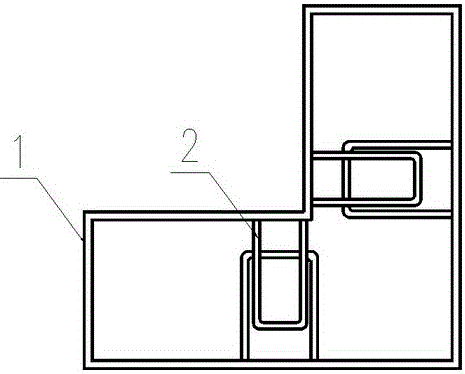
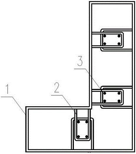
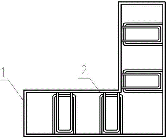
[0032] A schematic cross-sectional view of an embodiment of the L-shaped steel member proposed by the present invention, as figure 1 , the L-shaped steel member includes a steel piece 1 and a U-shaped connector 2, and the U-shaped connector 2 is connected (welding or other methods) on the long-side steel plate of the steel piece 1 (that is, each long-side steel plate is connected with a U-shaped Connecting piece 2), the U-shaped connecting piece on the opposite side is overlapped together; the connecting piece is arranged at a certain interval along the longitudinal direction of the steel piece, figure 1 The middle is the setting of the connecting piece at one section of the steel piece; the connecting piece 2 is on both sides of the corner of the L-shaped steel piece, forming an area at the corner, the adjacent two sides of this area ar...


PUM


Abstract

The invention relates to an L-shaped steel member and belongs to the technical field of steel structures. The L-shaped steel member comprises a steel piece and connecting pieces. The connecting pieces are connected with steel plates on the long edges of the steel piece. The connecting pieces are in a U shape. The U-shaped connecting pieces on the opposite sides are in lap joint. By means of the L-shaped steel member, the structural stress performance and the industrial level are improved.

Description

technical field [0001] The invention relates to an L-shaped steel component. Background technique [0002] The steel structure has a high degree of industrialization and good mechanical performance, and it is more and more widely used in building structures. The shear wall has high bearing capacity and high lateral stiffness, and is the main lateral force-resistant structural component of high-rise structures. [0003] Composite members such as concrete-filled steel tube columns are generally square or circular in cross-section, giving full play to the confinement effect of steel tubes. The steel-concrete composite shear wall has the performance advantages of the shear wall, and also has the advantages of the manufacture and installation of the steel structure; the ratio of the long side to the short side of the section of the steel-concrete composite shear wall is greater than 1, and the restraining effect of the steel is reduced. Generally, the components are separated b...

Claims


Application Information

Patent Timeline
Patent Type & Authority Applications(China)
IPC IPC(8): E04B2/86
CPCE04B2/8623
Inventor 初明进
Owner 初明进
Why Eureka
Try Eureka