Uniform temperature type polysilicon reducing furnace

A polysilicon and reduction furnace technology, applied in silicon compounds, sustainable manufacturing/processing, inorganic chemistry, etc., can solve the problems of high energy consumption, small output per furnace, thermal deformation of thick tube sheets, etc. Reduce welding workload and solve the effect of thermal deformation

Active Publication Date: 2012-04-25
江苏中圣压力容器装备制造有限公司
View PDF5 Cites 9 Cited by
  • Summary
  • Abstract
  • Description
  • Claims
  • Application Information

AI Technical Summary

Problems solved by technology

[0014] The purpose of the present invention is to design an arc-shaped and uniform temperature polysilicon reduction furnace for the problems of low single-furnace output and high energy consumption existing in the current polysilicon reduction furnace, and use the principle of porous capillary for the connection between the thick tube plate and the electrode seat and cooling, avoiding the high-temperature electrode from being burned out, reducing the welding workload, and solving the problem of thermal deformation of the thick tube plate

Method used


Image

  • Uniform temperature type polysilicon reducing furnace
  • Uniform temperature type polysilicon reducing furnace
  • Uniform temperature type polysilicon reducing furnace

Examples


Embodiment Construction

[0041] The present invention will be further described below in conjunction with the accompanying drawings and embodiments.

[0042] Such as figure 1 -6 shown.

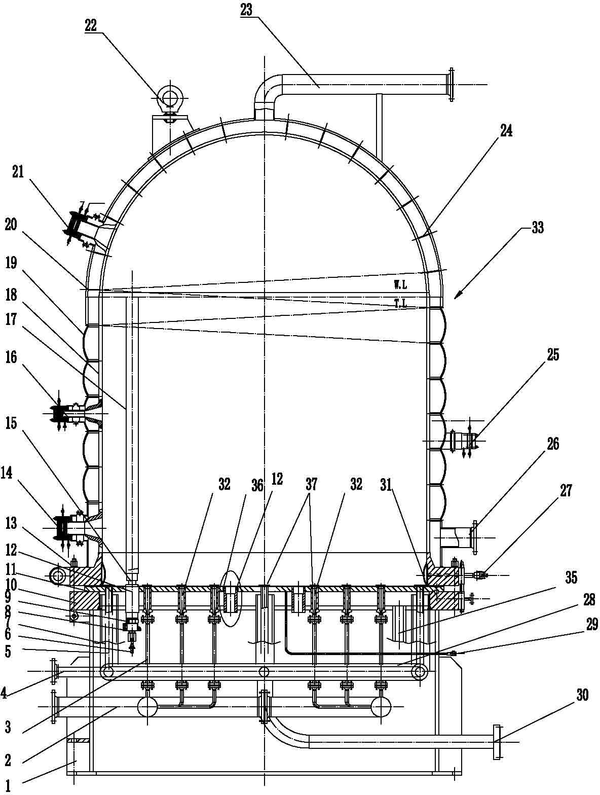
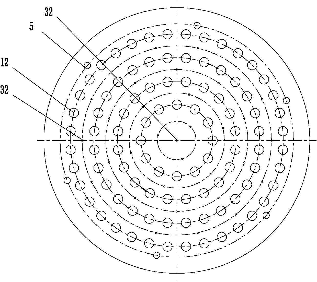
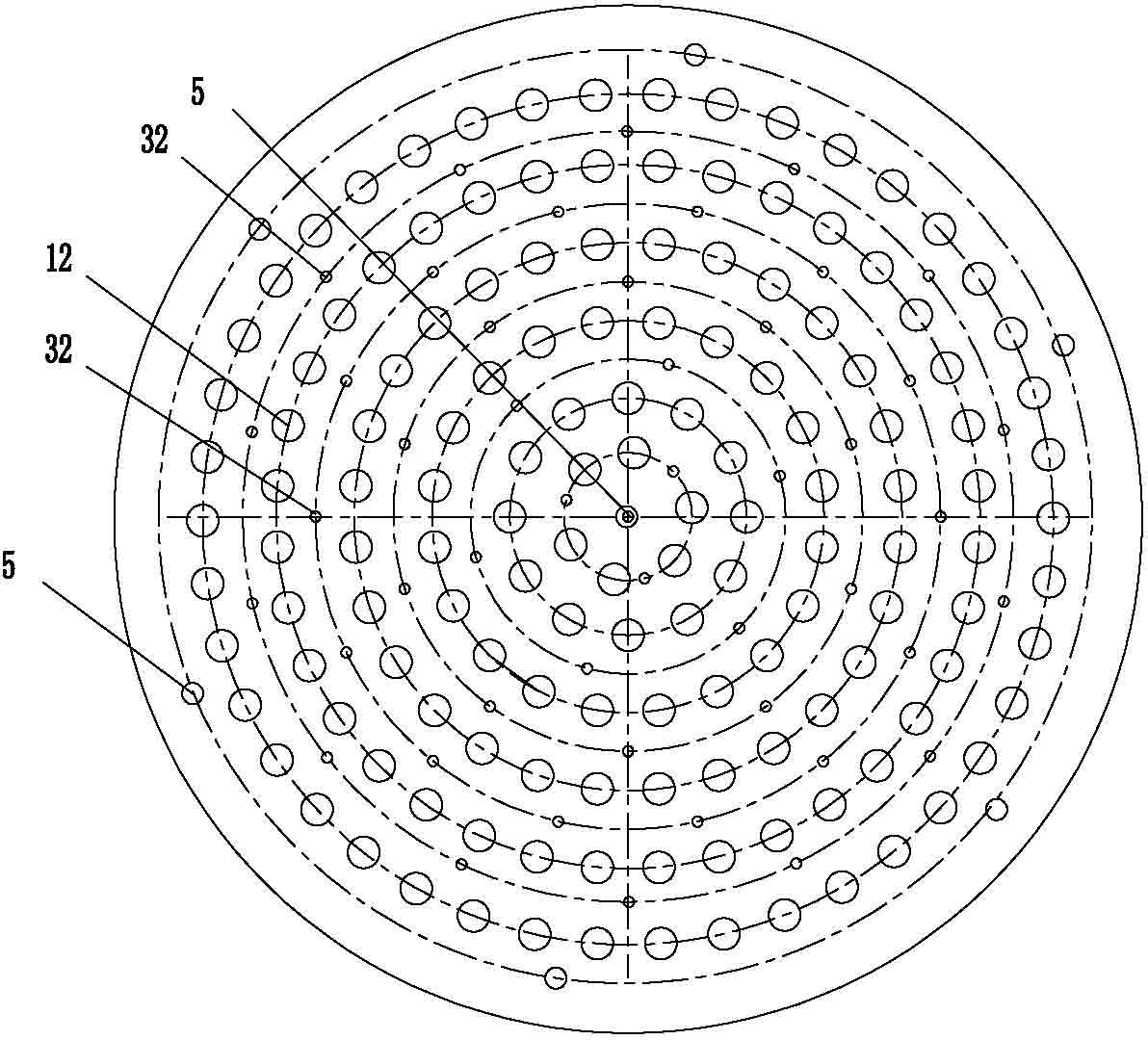
[0043] A bell type large-scale polysilicon reduction furnace, which includes a support 1, a water jacket tube plate 10 and a furnace body 33, the water jacket tube plate 10 is installed on the support 1, and the furnace body 33 is installed on the water clamp through a flange The casing tube plate 10 is provided with a water jacket 31 on the flange connecting the furnace body 33 and the water jacket tube plate 10, and the water inlet 27 of the water jacket 31 is connected with the cooling water source, and the other part of the water inlet 27 of the water jacket 31 One end is correspondingly provided with the water outlet 27 of water jacket 31 and is connected with cooling water drain pipe; Described furnace body 33 is made up of furnace cylinder inner wall 18 and arc-shaped furnace outer cylinder 19 and spherica...


PUM

PropertyMeasurementUnit
pore sizeaaaaaaaaaa
pore sizeaaaaaaaaaa

Abstract

An uniform temperature type polysilicon reducing furnace comprises a bearer (1), a water jacket tube plate (10) and a furnace body (33), wherein the water jacket tube plate (10) is installed on the bearer (1); and the furnace body (33) is installed on the water jacket tube plate (10) through a flange. The uniform temperature type polysilicon reducing furnace is characterized in that the furnace body (33) is composed of a furnace cylinder inner wall (18), arc-shaped furnace outer cylinder (19) and a spherical furnace outer cylinder (20), wherein the furnace cylinder inner wall (18) facing the furnace chamber is provided with a thermoreflectance coating; Spirally arranged shoe plates (24) are installed both between the furnace cylinder inner wall (18) and the arc-shaped furnace outer cylinder (19) and between the furnace cylinder inner wall (18) and the spherical furnace outer cylinder (20). The bottom of the arc-shaped furnace outer cylinder (19) is provided with a cooling water outletand inlet (26) for cooling the furnace body (33). The cooling water between the furnace cylinder inner wall (18) and the arc-shaped furnace outer cylinder (19) and the spherical furnace outer cylinder (20) spirally rises to a steam outlet (23) arranged at the top of the furnace body and is discharged out of the furnace body (33). The joint of an electrode sleeve (12) and a water jacket tube plate(10) is provided with a silk screen or semicircular capillary cooling component (36). The furnace core space outlets of a raw material gas nozzle (32) and a tail gas outlet duct (5) are provided withporous or cancellate filter mantles (37). The furnace provided by the invention has advantages of large size, good cooling effect of the thick tube plate, uniform furnace velocity field and temperature field and remarkable energy-saving effect.

Description

technical field [0001] The invention relates to a solar silicon rod production equipment, in particular to a polysilicon reduction furnace, specifically an arc-shaped uniform temperature polysilicon reduction furnace with a diameter of more than 3 meters. Background technique [0002] At present, in the severe situation of high crude oil prices in the world, saving energy and improving energy utilization efficiency have attracted great attention from all countries in the world. In addition, because the energy needed by human beings mainly depends on oil, coal, etc., thermal power and industrial production emit a large amount of CO 2 , global warming is evident. The energy crisis and the deterioration of the ecological environment have become the bottleneck of the development of human civilization. my country's rapidly developing economy and people's living standards continue to improve, energy demand has increased significantly, and carbon emissions have increased day by ...

Claims


Application Information

Patent Timeline
Patent Type & Authority Applications(China)
IPC IPC(8): C01B33/035
CPCY02P20/10
Inventor 郭宏新刘丰刘世平马明何松陈瑜田朝阳肖天菊
Owner 江苏中圣压力容器装备制造有限公司
Why Eureka
Try Eureka