Power unit support structure

A technology of power unit and support structure, applied in power plant, vibration suppression adjustment, shock absorber, etc., can solve the problems such as weakening and infeasibility of idling vibration damping effect

Inactive Publication Date: 2010-01-06
SUMITOMO RIKO CO LTD
View PDF2 Cites 4 Cited by
  • Summary
  • Abstract
  • Description
  • Claims
  • Application Information

AI Technical Summary

Problems solved by technology

However, there is an unavoidable problem that if tuning is performed in this way, high dynamic elasticity may lead to a situation where idle vibration with a slightly higher frequency than crankshaft vibration is input in the same roll direction, and may cause a Significantly reduced vibration damping
Therefore, the invention disclosed in Japanese Patent Application Laid-Open No. 11-190383 is not feasible in consideration of the importance of the damping effect on idling vibration.

Method used


Image

  • Power unit support structure
  • Power unit support structure
  • Power unit support structure

Examples


Embodiment Construction

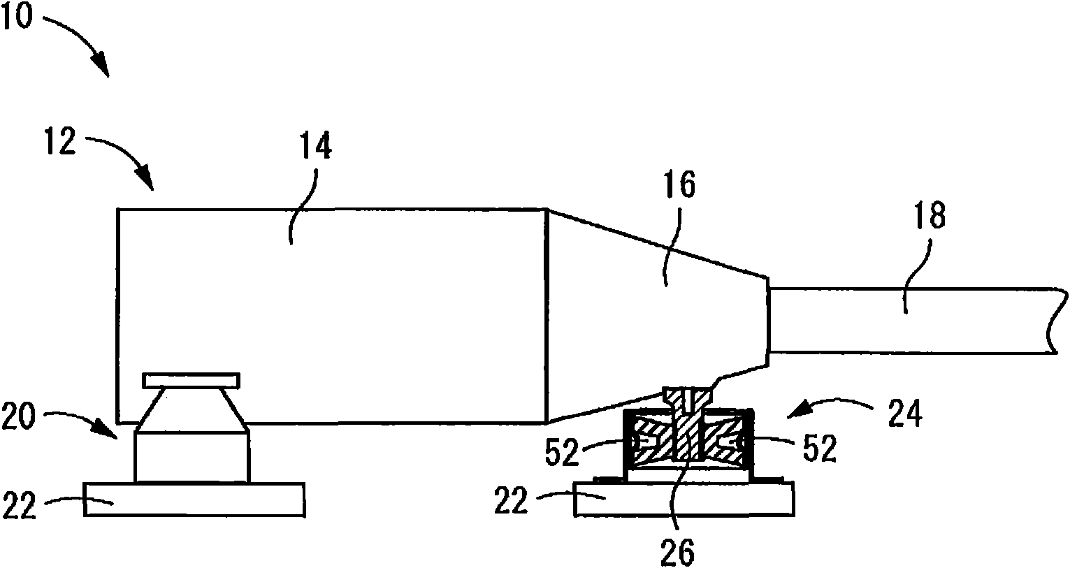
[0045] figure 1 is a side view showing the entire power unit support structure 10 according to the first embodiment of the present invention in a simplified manner. The power unit 12 is a power unit for an automobile of FR design, and the power unit 12 includes an engine unit 14 provided as an internal combustion engine and a drive train unit 16 provided as a gearbox. The output and torque generated by the engine unit 14 are adjusted by the gear train of the drive train unit 16 to a level of output and torque required to drive the vehicle, and are output to an output shaft (not shown), and then as rotational driving force via The propeller shaft 18 is transmitted from the output shaft to the drive wheels, ie the rear wheels.

[0046] To illustrate more specifically, the power unit 12 is oriented lengthwise in the vehicle fore-and-aft direction such that the propeller shaft 18 extends in a direction that is aligned with the vehicle fore-and-aft direction ( figure 1 The left a...


PUM


Abstract

A power unit support structure (10) adapted to provide vibration-damped support of an power unit (12) of an automobile of FR longitudinal engine design on a vehicle body via engine mounts situated at two locations towards a vehicle front end and one location towards a vehicle back end, respectively. Of the engine mounts disposed at the three locations, a fluid-filled vibration-damping device (25, 66, 92) exhibiting vibration-attenuating action based on flow action of non-compressible fluid filling the interior thereof is employed as a rear engine mount (24, 60, 90) disposed at the vehicle back end, and the vibration-attenuating action based on the flow action of the non-compressible fluid is exhibited against vibration input in a vehicle longitudinal direction.

Description

technical field [0001] The present invention generally relates to a power unit support structure suitable for installing a vibration-damping support for an automobile power unit on a vehicle body, and in particular to a power unit suitable for providing effective damping for the yawing vibration of the power unit. unit support structure. Background technique [0002] As is known in the art, in order to reduce the transmission of vibrations to the vehicle body, automotive power units, which integrally contain the engine and drive train, are provided with damping supports at several locations on the vehicle body by the engine mounts. In particular, in the case of a longitudinally mounted engine of an FR (front engine / rear wheel drive) vehicle, the front-rear dimension of the power unit will be larger than the vehicle left-right dimension of the power unit, and the weight of the power unit near the front of the vehicle will exceed that near the rear. the weight of the drive tr...

Claims


Application Information

Patent Timeline
Patent Type & Authority Applications(China)
IPC IPC(8): B60K5/12F16F15/023
CPCF16F13/16F16F13/1463
Inventor 滨田真彰井原芳雄石川亮太
Owner SUMITOMO RIKO CO LTD
Why Eureka
Try Eureka