Power transmission

A technology of power transmission system and transmission device, which is applied in the field of power transmission system to achieve the effect of small friction loss

Inactive Publication Date: 2006-01-25
GIBBS TECH
View PDF0 Cites 0 Cited by
  • Summary
  • Abstract
  • Description
  • Claims
  • Application Information

AI Technical Summary

Problems solved by technology

This known configuration also necessitates cutting away the bell housing or derailleur housing to make room for the chain or belt

Method used


Image

  • Power transmission
  • Power transmission
  • Power transmission

Examples


Embodiment Construction

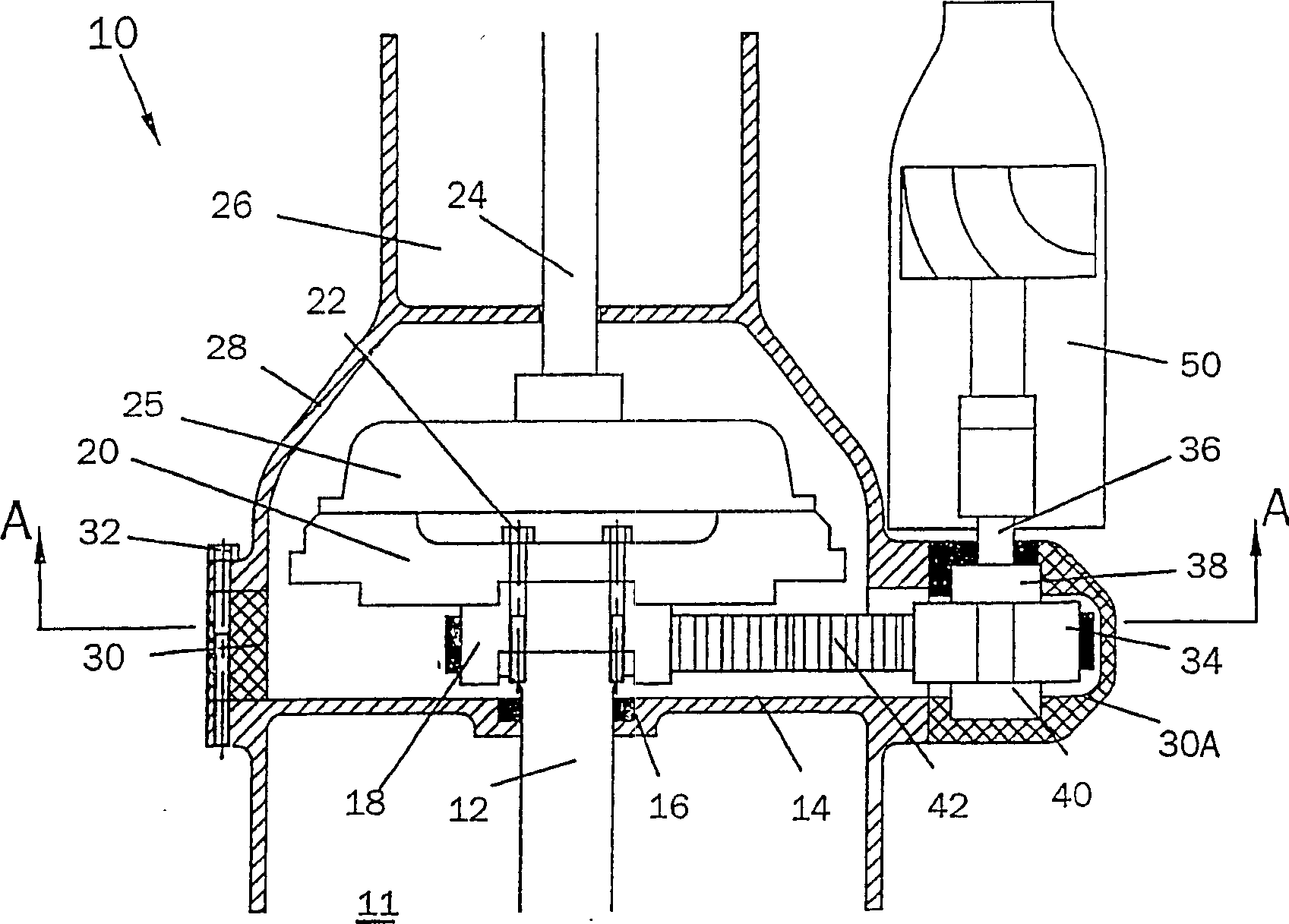
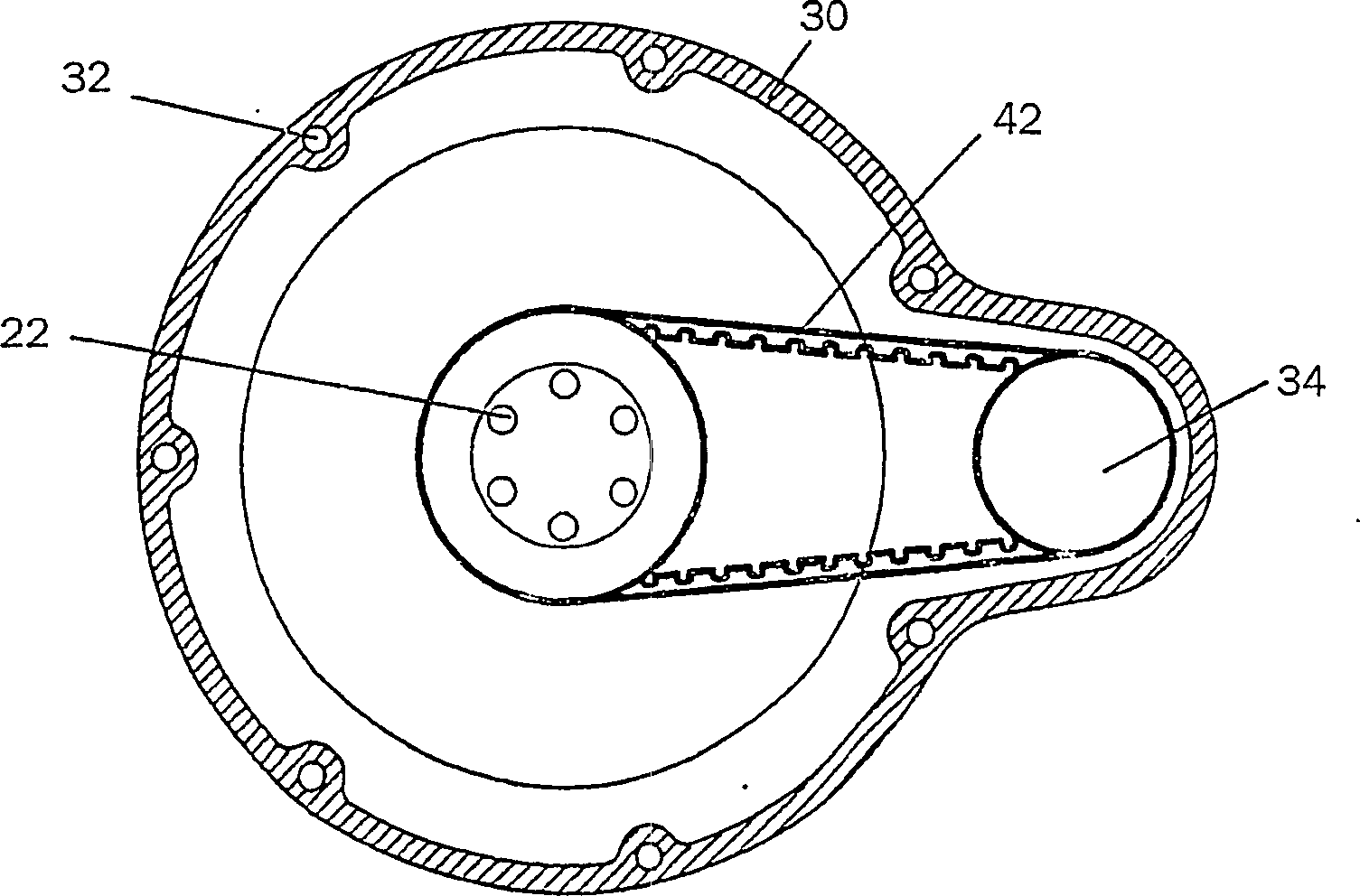
[0021] first as figure 1 and figure 2 As shown, the first embodiment of the powertrain of the present invention includes an engine 11 and a transmission 26 in line with the crankshaft 12 of the engine. The engine and transmission provide drive to at least the rear wheels (not shown) of the amphibian using a conventional differential (not shown). The power take-off 10 provides drive to the vehicle's water propulsion means, such as a water jet 50 .

[0022] The crankshaft 12 of the engine passes through a hole in the end of the engine casing 14 . A seal 16 is arranged in the hole to realize the sealing between the crankshaft 12 and the engine casing 14 . Drive sprocket 18 and flywheel 20 are mounted on the end of crankshaft 12 outside of engine casing 14 and are fixedly secured to crankshaft 12 by a turn of bolts 22 . A drive sprocket 18 is fixed between the end of the crankshaft 12 and a flywheel 20 . A clutch 25 is mounted on the face of the flywheel 20 in a conventional...


PUM


Abstract

An amphibious vehicle power train comprises engine (111) with crankshaft (112) and solid or fluid flywheel (120); a transmission (26, figure 1) arranged in line with the crankshaft, with an input shaft (24, figure 1) driven from the flywheel; and a power take off (PTO) (110) for driving shafts (136 and 158) and marine propulsion means (50, figure 1). The PTO comprises a driving sprocket (118) attached to the crankshaft, a chain or belt (142), and a driven sprocket (134). Bevel gears (154, 156) are provided to convert transverse engine crankshaft rotation to longitudinal marine drive. Figures 1 to 4 and 8 show embodiments for longitudinal engines. Figures 1 and 2 show drive from adaptor (18), figures 3 and 4 show drive from a flywheel with relocated ring gear (52). Figures 6 and 7 show alternative power take offs for a transverse engine, using bevel gears (218, 219) for power transmission.

Description

technical field [0001] The present invention relates to a power train for an amphibious vehicle, said power train comprising an engine and an in-line transmission, a power take-off between the engine and the in-line transmission of the vehicle, and said power take-off Commonly known as sandwich (sandwich) power take-off device. The invention also relates to an amphibious vehicle having such a drive train. Background technique [0002] In a conventional motor vehicle, the drive train has an engine and an in-line transmission whose drive shaft or first shaft is driven by a flywheel via a clutch. Additionally, where the transmission includes an automatic transmission, drive to the drive shaft may be accomplished using a fluid flywheel known as a torque converter. In known sandwich PTO configurations, the drive shaft of the transmission extends between the clutch or fluid flywheel and the transmission housing, and the drive in the form of a sprocket is mounted between the clut...

Claims


Application Information

Patent Timeline
Patent Type & Authority Patents(China)
IPC IPC(8): B60K17/28B60F3/00B60K6/30
CPCB60F3/0007B60K17/28
Inventor 艾伦·蒂莫西·吉布斯特伦斯·詹姆斯·罗伊克罗夫特
Owner GIBBS TECH
Why Eureka
Try Eureka