Longitudinal engine mount installation structure

A technology of engine suspension and installation structure, which is applied in the direction of power device, transportation and packaging, jet propulsion device, etc., can solve the problems of restricting production rhythm, slow production rhythm, difficult assembly, etc., achieve shortening production rhythm, improve production efficiency, Optimize the effect of suspension structure and installation method

Inactive Publication Date: 2015-12-30
ANHUI JIANGHUAI AUTOMOBILE GRP CORP LTD
View PDF6 Cites 0 Cited by
  • Summary
  • Abstract
  • Description
  • Claims
  • Application Information

AI Technical Summary

Problems solved by technology

Due to the angle between the suspension rubber body and the mounting surface of the engine support beam, it is difficult to assemble, and the number of bolts is 4, so the production cycle is slow and restricts the production cycle

Method used


Image

  • Longitudinal engine mount installation structure
  • Longitudinal engine mount installation structure
  • Longitudinal engine mount installation structure

Examples


Embodiment Construction

[0035] The technical solution of the present invention is described in detail below through the examples, and the following examples are only exemplary and can only be used to explain and illustrate the technical solution of the present invention, rather than being interpreted as a limitation to the technical solution of the present invention.

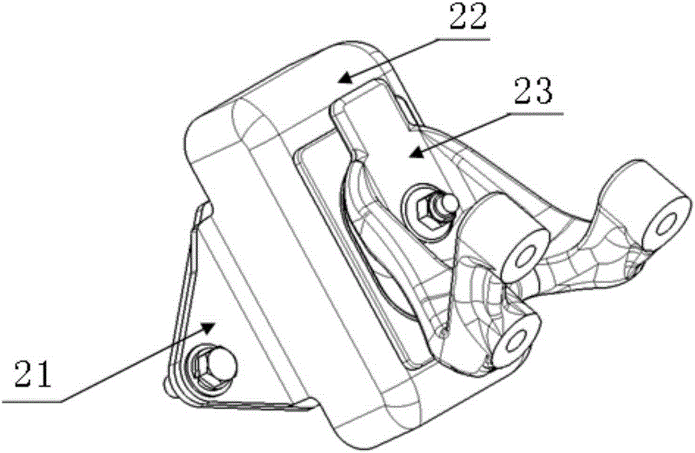
[0036] The invention provides a vertical engine suspension installation structure, such as Figure 6 to Figure 10 As shown, it includes an engine mount rubber body 01, an engine mount cover plate 02 and a transition structure 03; there is an included angle of a set angle between the engine mount rubber body 01 and the horizontal plane; the function of the included angle is to ensure The engine mount is oblique mount.

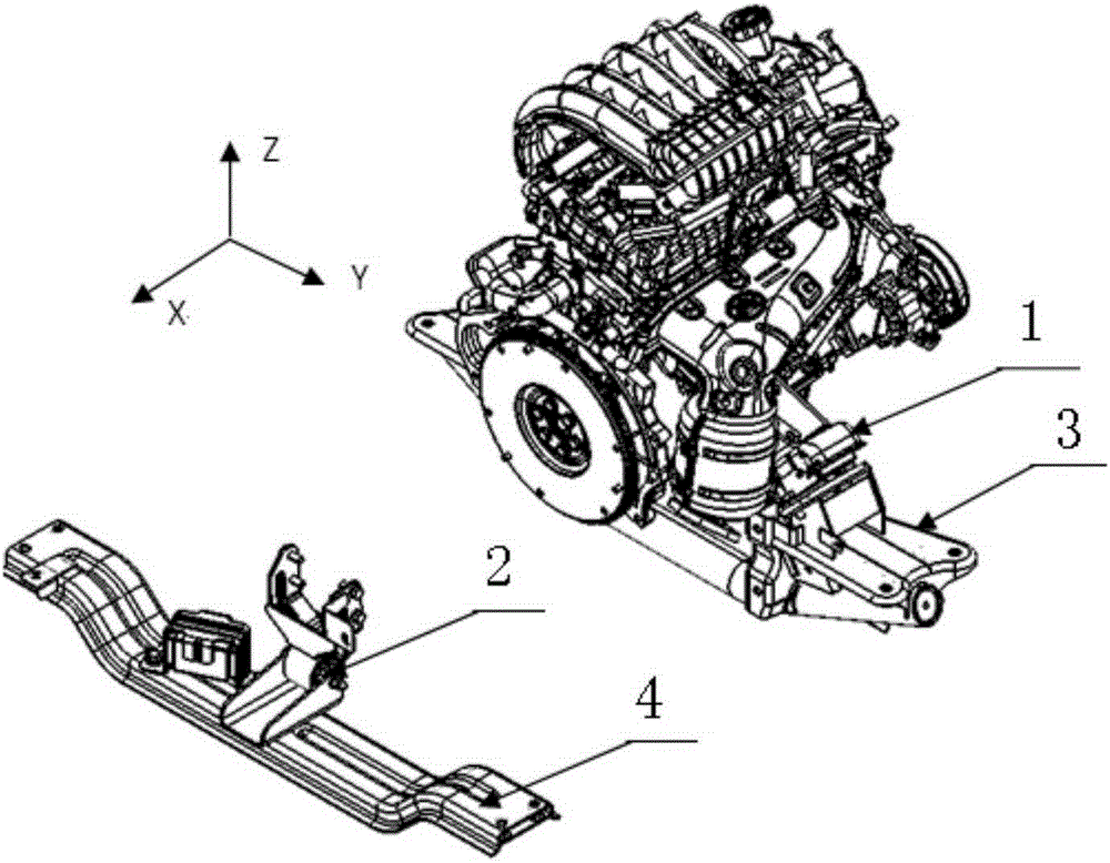
[0037] In the documents of this application, all references to the X direction, Y direction and Z direction are the coordinate system directions, wherein the Z direction is the direction perpendicular to the X direction ...


PUM


Abstract

The invention relates to a longitudinal engine mount installation structure. The structure comprises an engine mount rubber main body, an engine mount cover plate and a transition structure, wherein the engine mount rubber main body comprises a rubber main body lower installation plate, main body rubber and a rubber main body upper installation plate; the rubber main body upper installation plate comprises a bottom plate and an installation bolt; the installation bolt is a bent bolt and comprises a fixing part and an installation part; the installation part is perpendicular to the horizontal plane; the transition structure comprises an installation surface and a connection surface; a via hole running through the installation surface and the connection surface is formed in the transition structure; the installation part passes through the via hole. The structure has the beneficial effects that the production takt is shortened and the production efficiency is improved by improving the engine mount rubber main body structure, changing the installation bolt structure, replacing a mount support with the transition structure and optimizing the mount structure and the way of installation.

Description

technical field [0001] The invention belongs to the technical field of engine mounts, in particular to a longitudinally mounted engine mount installation structure. Background technique [0002] Longitudinal powertrain mounts are widely used, suitable for some cars, most MPVs, pickups, light trucks and other models. [0003] The layout of the longitudinal powertrain mount is as follows: figure 1 As shown, the entire powertrain is arranged along the forward direction of the vehicle. Generally, there is an included angle between the crankshaft and the forward direction of the vehicle (because the powertrain generally has an included angle), and a pair of oblique engine mounts 1 are symmetrically arranged on the front side of the engine, in a V-shaped arrangement (the included angle is generally 20 degrees to 50 degrees), a gearbox suspension 2 is arranged at the rear end of the gearbox. [0004] Usually, when the vertical powertrain is assembled, due to the angle between th...

Claims


Application Information

Patent Timeline
IPC IPC(8): B60K5/12
Inventor 彭宜爱胡俊生刘子萌
Owner ANHUI JIANGHUAI AUTOMOBILE GRP CORP LTD
Why Eureka
Try Eureka