Engine crank pulley structure

a crank pulley and engine technology, applied in the direction of machines/engines, gearing, hoisting equipment, etc., can solve the problems of engine intruding into the vehicle cabin, increasing the amount of crush stroke (crush space) and achieve the effect of sufficient crush spa

Pending Publication Date: 2022-10-06
MAZDA MOTOR CORP
View PDF1 Cites 0 Cited by
  • Summary
  • Abstract
  • Description
  • Claims
  • Application Information

AI Technical Summary

Benefits of technology

[0022]The present invention can ensure a sufficient crush space for front-end collisions

Problems solved by technology

That is, this might cause a vehicle rear side end of the engine to contact a dash panel defining between the engine room and the vehicle cabin or cause the engine to intrude into the vehicle cabin.
In the event of a front-end collision, this

Method used


Image

  • Engine crank pulley structure
  • Engine crank pulley structure
  • Engine crank pulley structure

Examples


Embodiment Construction

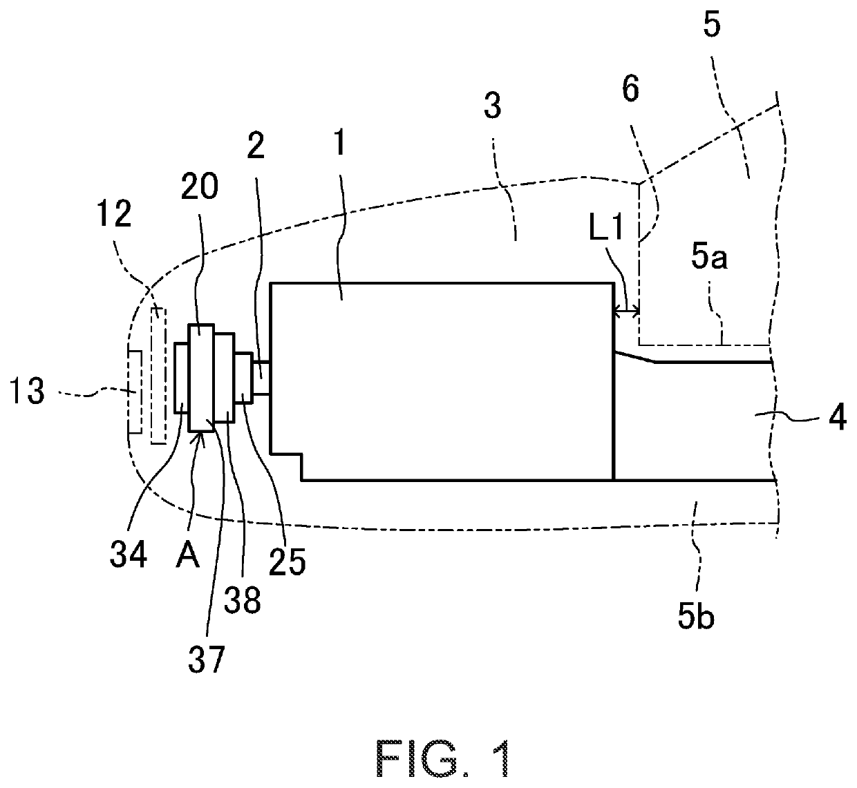
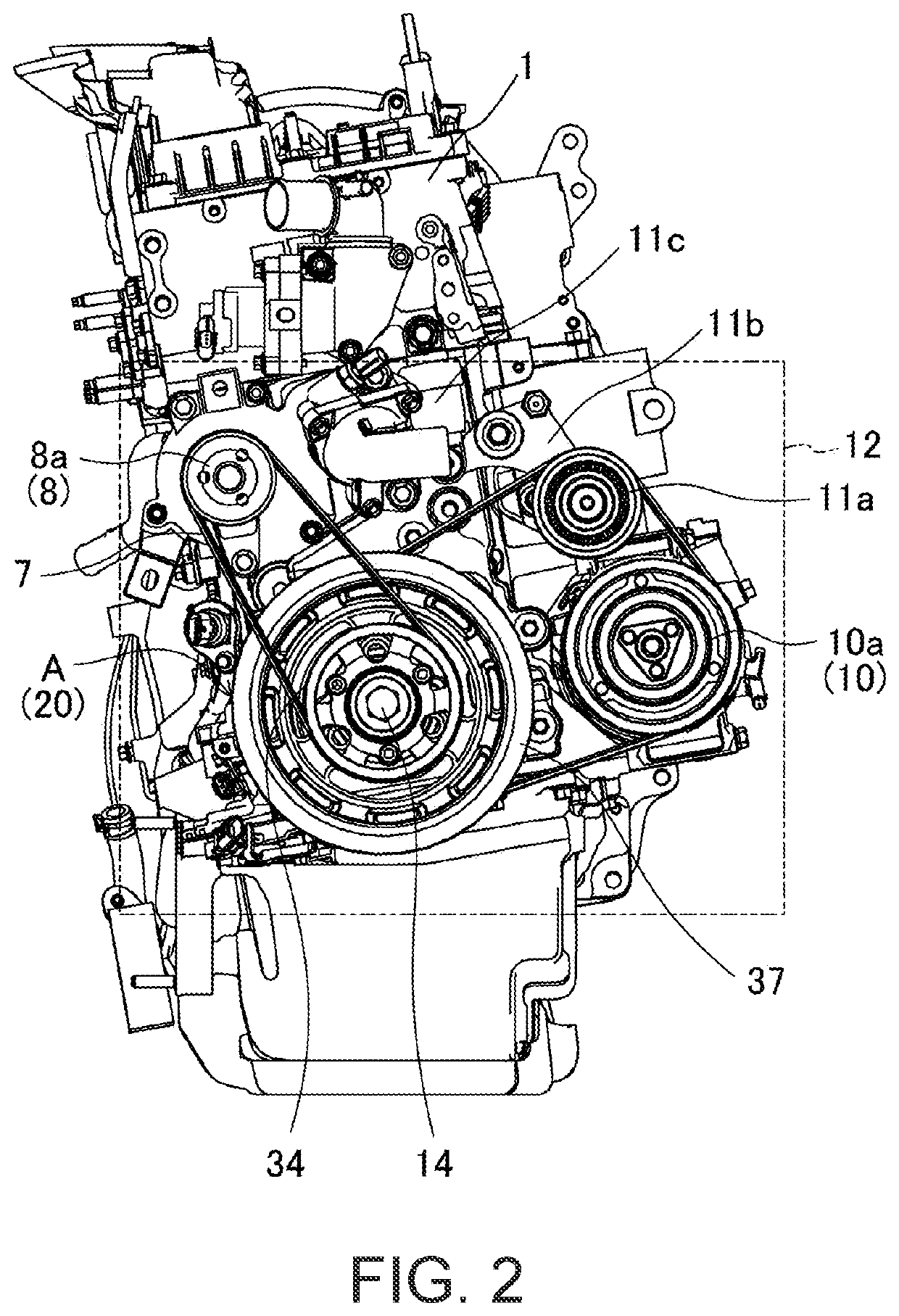
[0031]Hereinafter, a detailed description will be given of an embodiment of the present invention with reference to drawings. The following description of a preferred embodiment is merely illustrative in nature and in no way intended to limit the present invention, its applications, or its uses. In the present description, a direction in which the vehicle moves forward and backward is referred to as a “front-rear direction,” and the forward side in that direction is referred to as a “front side” while the backward side in that direction is referred to as a “rear side.” A vehicle width direction is referred to as a “right-left direction,” and the right side in that direction as viewed from the vehicle rear side is referred to as a “right side,” while the left side in that direction as viewed from the vehicle rear side is referred to as a “left side.” In FIGS. 1 and 2, an engine 1 and an engine crank pulley structure A are shown by solid lines, and the other components are shown by do...


PUM


Abstract

An engine crank pulley structure disposed at a vehicle front side of a longitudinal engine includes: a front pulley that transmits crank rotational force to the water pump via a belt; a rear pulley that is disposed at a vehicle rear side of the front pulley and transmits a crank rotational force to a compressor via a belt; and a connecting portion that connects the front pulley and the rear pulley, the connecting portion crushing and deforming in a vehicle front-rear direction as a collision load toward the vehicle rear side is applied to it. An outer diameter of the front pulley is smaller than an inner diameter of the rear pulley.

Description

TECHNICAL FIELD[0001]The present invention relates to an engine crank pulley structure.BACKGROUND ART[0002]A longitudinal engine has multiple cylinders arranged in a vehicle front-rear direction and is thus longer in the vehicle front-rear direction than transverse engines. That is, when the longitudinal engine is accommodated in an engine room located at a vehicle front side of a vehicle cabin, the engine room will often have a small space.[0003]Also, the longitudinal engine includes a crank pulley disposed at the vehicle front side and a transmission disposed at a vehicle rear side.[0004]In the event of a collision from the vehicle front side (hereinafter referred to as a “front-end collision”), a collision load toward the vehicle rear side is applied to the crank pulley, causing the crank pulley to push the engine toward the vehicle rear side. That is, this might cause a vehicle rear side end of the engine to contact a dash panel defining between the engine room and the vehicle c...

Claims


Application Information

Patent Timeline
IPC IPC(8): F02B67/06F16H55/36
CPCF02B67/06F16H55/36F16H2007/0865B60K25/00B60K25/02
Inventor FURUTANI, MASAYUKIHIRATA, KOICHINISHIZAKA, SATOSHITOKUSHIMA, KAZUHIROFUJINO, YUZO
Owner MAZDA MOTOR CORP
Why Eureka
Try Eureka