
Lifting device of engineering machine and telescopic type belt delivery wagon with same

A lifting device and construction machinery technology, which is applied in the direction of conveyors, motor vehicles, conveyor objects, etc., can solve the problems that cannot meet the actual needs, and achieve the effect of simple and compact lifting device

Active Publication Date: 2011-11-09
SANY AUTOMOBILE MFG CO LTD +1
View PDF1 Cites 0 Cited by
  • Summary
  • Abstract
  • Description
  • Claims
  • Application Information

AI Technical Summary

Problems solved by technology

Therefore, the structure in which the slewing head support seat is fixed on the main slewing support platform cannot meet the actual needs more and more

Method used


Image

  • Lifting device of engineering machine and telescopic type belt delivery wagon with same
  • Lifting device of engineering machine and telescopic type belt delivery wagon with same
  • Lifting device of engineering machine and telescopic type belt delivery wagon with same

Examples


Embodiment

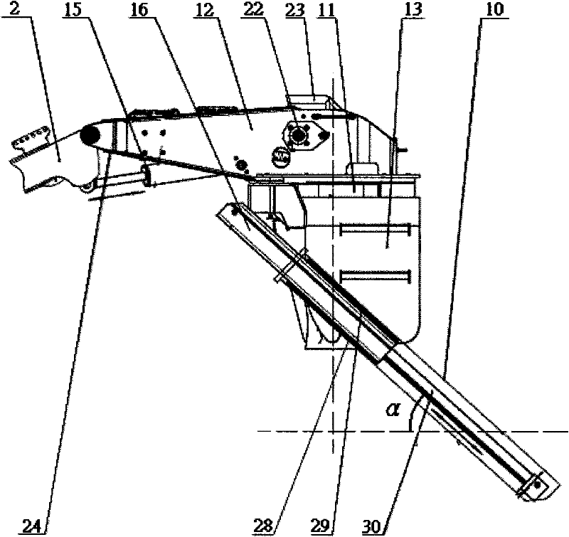
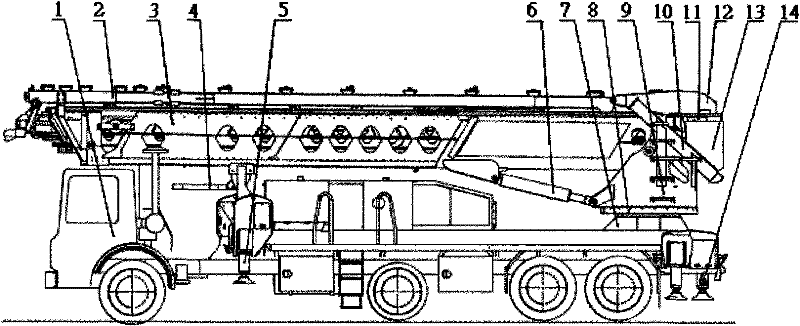
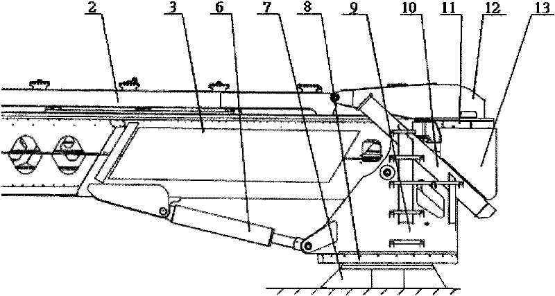
[0017] like figure 1 As shown, it is a structural schematic diagram of a lifting device of a construction machine provided by the present invention, which includes a rotary head 12 of the discharge device with a rotary device 11 at the bottom, and a rotary head 12 on both sides of the rotary head 12 of the discharge device. Rotary head welding frame 24, the discharge end of the feeding belt conveyor 2 is fixed to the cantilever end of the rotary head welding frame 24 with a rotating shaft, and idlers, drive motors 22, and discharge sleeves 23 are installed on the welding frame 24 , Blanking hopper, driving drum, etc. The cylinder body end of feeder lifting oil cylinder 15 is fixed on the symmetrical centerline position of rotary head welding frame 24 with rotating shaft, and the piston rod end is then fixed on the discharge end symmetrical centerline position of feeder 2 with rotating shaft.

[0018] The present invention enlarges and strengthens the original slewing head sup...


PUM


Abstract

The invention relates to a lifting device of an engineering machine and a telescopic type belt delivery wagon with the same. The lifting device comprises a discharging device turning head provided with a turning device at the bottom, wherein both sides of the discharging device turning head are provided with turning head welding frames, the cylinder body end of a feeding device lifting oil cylinder is arranged on the turning head welding frame through a rotating shaft, and the piston rod end of the feeding device lifting oil cylinder is arranged on a feeding device through the rotating shaft;and the turning device is arranged on the top of a box body frame. The lifting device is characterized in that the both sides of the box body frame are provided with rectangle-shaped slideways fixed on a main turning support table, and rectangle-shaped bracing tubes which are fixed on the box body frame are arranged on the rectangle-shaped slideways and internally provided with feeding device setting oil cylinders; and in addition, the lifting device of the engineering machine can be applied to the telescopic type belt delivery wagon. The lifting device of the engineering machine of a feedingconveyor is simple, compact and more flexible and reliable, can save trouble and labour and is convenient to widely use for the telescopic type belt delivery wagon.

Description

technical field [0001] The invention relates to construction machinery, in particular to a construction machinery lifting device for a telescopic belt conveyor vehicle, and also to a telescopic belt conveyor vehicle with such a construction machinery lifting device. Background technique [0002] Currently known belt conveyor systems usually set the feed belt conveyor above the first arm receiving end of the main belt conveyor through a hinged slewing device and a slewing head support seat. The oil cylinder on the support seat of the remote control rotary head can slightly lift the end of the discharge arm to make it arch up to a certain height and clearance, and with the help of the lifting and turning of the main belt conveyor, the entire feeding belt conveyor reaches the truck. Desired position on the side or rear. [0003] The patent No. is the patent of US6378686, is that the discharge end of the feeding belt conveyor is connected to the rotary head of the discharge dev...

Claims


Application Information

Patent Timeline
Patent Type & Authority Patents(China)
IPC IPC(8): B65G21/14B65G15/26B65G41/00B60P3/00
Inventor 亚伦·马凯马丁·古逊鲍尔马丁·迈尔吴国亮
Owner SANY AUTOMOBILE MFG CO LTD
Learn More