Terminal protecting component of electric compressor

A technology for electric compressors and protective components, which is applied in the direction of machines/engines, pump components, mechanical equipment, etc. It can solve problems such as narrow intervals, hindering the bypass operation of the cord group 20, and difficulty in performing it, and achieves the effect of preventing poor insulation

Inactive Publication Date: 2010-01-06
SANYO ELECTRIC CO LTD
View PDF2 Cites 6 Cited by
  • Summary
  • Abstract
  • Description
  • Claims
  • Application Information

AI Technical Summary

Problems solved by technology

like Figure 8 As shown, the distance between the flexible wire receiving piece 11 and the side edge of the flexible wire outlet hole 9 is narrow, and as Figure 7 As shown, since the front end of the cord receiving sheet 11 has corners, it is difficult to bypass the cord group 20.
Furthermore, a protrusion 9a is provided along the peripheral portion of the cord lead-out hole 9, and the lower end portion of the protrusion 9a prevents the cord group 20 from being bypassed.

Method used


Image

  • Terminal protecting component of electric compressor
  • Terminal protecting component of electric compressor
  • Terminal protecting component of electric compressor

Examples


Embodiment Construction

[0047] Embodiments of the present invention will be described below with reference to the drawings.

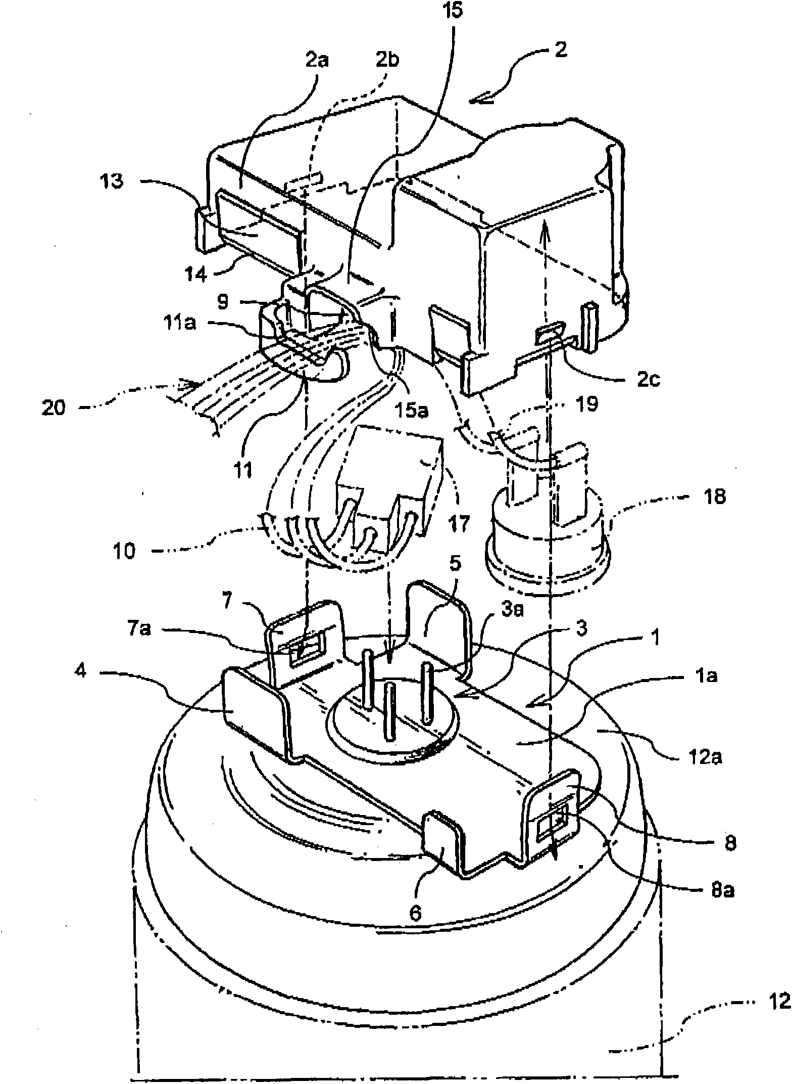
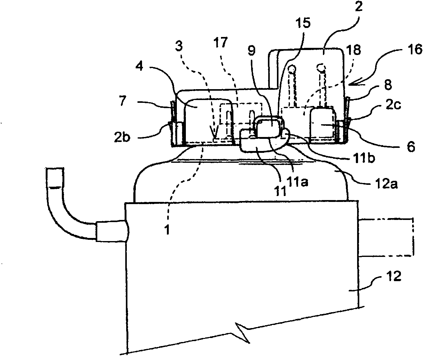
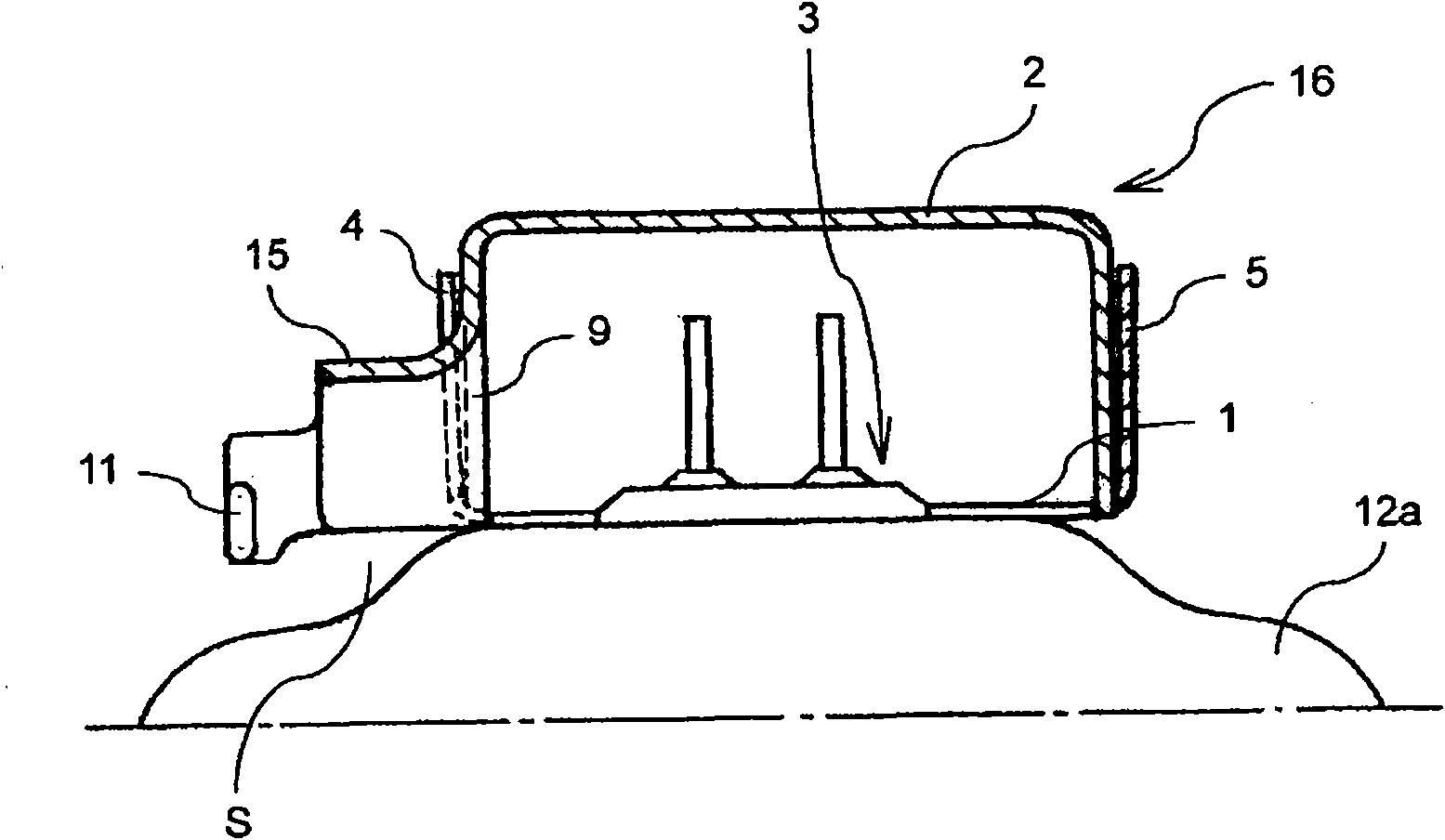
[0048] figure 1 It is a schematic exploded perspective view which shows embodiment of the terminal protection member of the electric compressor concerning this invention. right with Figure 6 In the conventional example shown, substantially the same members are denoted by the same reference numerals as those described above.

[0049] exist figure 1 Among them, 1 is a terminal guard made of steel plate, which penetrates the terminal 3 fixed to the top of the lid body 12a of the airtight container 12 and is attached to the lid body 12a. The side portion of the base plate 1a of the terminal guard 1 is vertically provided with blocking pieces 4, 5, and the side portion on the same side as the blocking piece 4 is vertically provided with a small blocking piece 6, and is vertically opposed at the end. Locking pieces 7, 8 are provided, and these locking pieces 7, 8 are formed wi...


PUM


Abstract

The present invention provides a terminal protecting component of an electric compressor, capable of restraining external water from immerging so as to prevent defective insulation, bad energization and the like, and an operation that flexible cord teams leaded out through a flexible cord lead-out hole bypass along a front end of a flexible cord carrying sheet and is supported by a dent on its upper end edge is easy to implement. In the electric compressor, the protecting component is composed of a terminal protecting piece (1) and a terminal cover (2) embedded and fixed on the terminal protecting piece (1) to protect a terminal (3) mounted on the top of an closed container (12), the terminal cover (2) is provided with a flexible cord lead-out hole (9) formed on a side face and a flexible cord carrying sheet (11) facing to the flexible cord lead-out hole, and the flexible cord carrying sheet (11) is arranged on an end lower than the lower end edge of the terminal cover (2) staggeredly. A front end portion (11b) of the flexible cord carrying sheet (11) is formed into a bending shape, a lower end portion of a visor-shaped prominency (15) formed around the flexible cord lead-out hole (9) is provided with a bending portion, thereby, the flexible cord teams are easy to bypass the front-end portion (11b).

Description

technical field [0001] The present invention relates to an electric compressor, and particularly relates to an improvement of a protection member for protecting a terminal attached to a closed container. Background technique [0002] Generally, an electric compressor accommodates a motor mechanism unit and a compression mechanism unit driven by the motor mechanism unit in an airtight container, and a terminal is installed in the airtight container, and the compression mechanism unit is activated by energizing the motor mechanism unit via the terminal. action. In addition, gas (usually coolant) is introduced into the compression mechanism through the introduction pipe and compressed, and at the same time, the high-pressure gas ejected from the airtight container is discharged to the outside through the discharge pipe. [0003] Since the cord terminal of the power supply is connected to the external electrode of said terminal outside the airtight container, this electrical co...

Claims


Application Information

Patent Timeline
IPC IPC(8): F04B39/00
Inventor 小林正英
Owner SANYO ELECTRIC CO LTD
Why Eureka
Try Eureka