Lighting device

A lighting device and optical lens technology, applied in the optical field, can solve the problems of light source module limitation, small irradiation range, short irradiation distance, etc., and achieve the effects of improving light collimation, increasing flexibility, and improving brightness

Inactive Publication Date: 2010-01-06
HONG FU JIN PRECISION IND (SHENZHEN) CO LTD +1
View PDF0 Cites 5 Cited by
  • Summary
  • Abstract
  • Description
  • Claims
  • Application Information

AI Technical Summary

Problems solved by technology

The light emitting angle of the light-emitting diode is generally 90 degrees to 120 degrees, and the light intensity in the center (the light emitting angle is about 0 degrees to 30 degrees) is relatively strong, while the surrounding light intensity is relatively weak, resulting in uneven light emitting from the entire light source module and irradiating The range is small, and the irradiation distance is relatively short, so that the application of the light source module with the LED is limited

Method used


Image

  • Lighting device
  • Lighting device

Examples


Embodiment Construction

[0009] The embodiments of the present invention will be further described in detail below in conjunction with the accompanying drawings.

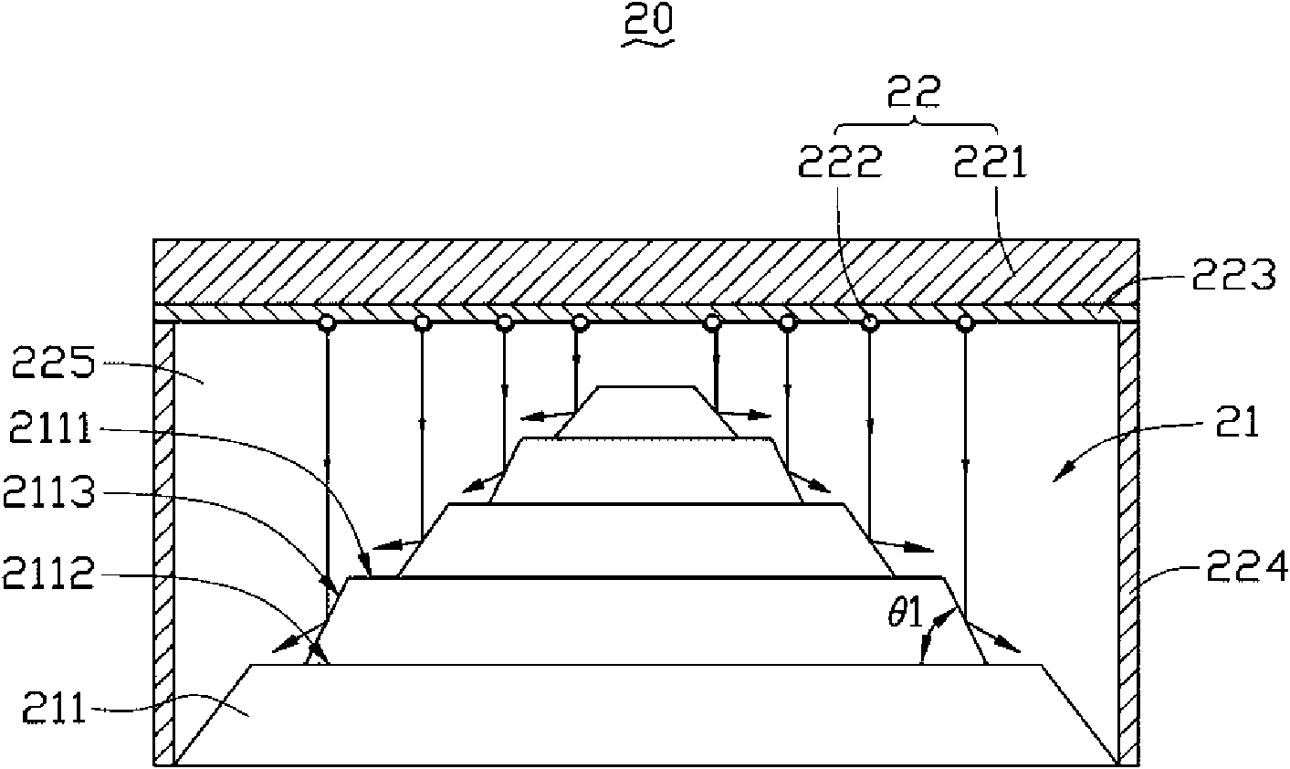
[0010] See figure 1 , A lighting device 20 provided by the first embodiment of the present invention includes: a first optical lens group 21 and a first light emitting module 22.

[0011] The first optical lens group 21 includes a plurality of truncated cone-shaped optical lenses 211 stacked in steps. Each optical lens 211 includes an upper surface 2111, a lower surface 2112 opposite to the upper surface 2111, and a side surface 2113 between the upper surface 2111 and the lower surface 2112. The upper surface 2111 and the side surface 2113 are reflective surfaces.

[0012] The first light emitting module 22 is disposed opposite to the first optical lens group 21 and includes a substrate 221 and a plurality of first light sources 222 disposed on the first substrate 221. In this embodiment, a reflective layer 223 is provided on the first substrate...


PUM


Abstract

A lighting device comprises a first optical lens group and a first light-emitting module. The first optical lens group comprises a plurality of platform optical lenses which are superposed in the ladder form; each optical lens comprises an upper surface, a lower surface opposite to the upper surface and a side surface between the upper surface and the lower surface; the side surface is a reflecting surface. The first light-emitting module comprises a first substrate and a plurality of first light sources arranged on the substrate; each first light source is opposite to one side surface of one optical lens; the side surface of the optical lens is used for reflecting the light emitted by the light source corresponding to the side surface.

Description

Technical field [0001] The present invention relates to the field of optical technology, and in particular to a lighting device. Background technique [0002] Currently, Light Emitting Diode (LED) has been widely used in many fields due to its low power consumption, long life, small size, and high brightness. Here, a new type of light-emitting diode can be found in the article Illumination With Solid State Lighting Technology in IEEE Journal on Selected Topics in Quantum Electronics, Vol. 8, No. 2, March / April 2002 by Daniel A. Steigerwald et al. [0003] The light emitting diode can be applied to a light source module, such as a warning light. The light output angle of the light-emitting diode is generally 90 degrees to 120 degrees. The light intensity in the center (the light output angle is about 0 degrees to 30 degrees) is relatively strong, and the surrounding light intensity is weak, resulting in uneven light output of the entire light source module. The range is small and ...

Claims


Application Information

Patent Timeline
Patent Type & Authority Applications(China)
IPC IPC(8): F21V5/04F21Y101/02
CPCG02B17/006G02B27/0922F21V7/0008G02B19/0028G02B27/0977G02B19/0066F21V7/0091F21W2111/00F21Y2101/02F21Y2115/10
Inventor 黄山福
Owner HONG FU JIN PRECISION IND (SHENZHEN) CO LTD
Why Eureka
Try Eureka