Heat exchanger

A technology of heat exchangers and micro-channel heat exchangers, which is applied in the direction of heat exchanger shells, indirect heat exchangers, heat exchanger types, etc., and can solve the problems of deterioration of overall machine performance, increased wind resistance, and increased power consumption of fans, etc. question

Active Publication Date: 2010-01-06
SANHUA HANGZHOU MICRO CHANNEL HEAT EXCHANGER
View PDF0 Cites 18 Cited by
  • Summary
  • Abstract
  • Description
  • Claims
  • Application Information

AI Technical Summary

Problems solved by technology

Specifically, due to the horizontal arrangement of the flat tubes, the condensed water on the fins will be blocked by the flat tubes and cannot flow down, and will accumulate on the fins and flat tubes, resulting in a decrease in heat transfer performance on the surface of the heat exchanger, and an increase in wind resistance. The power consumption increases, and the performance of the whole machine decreases. Even for the heat pump outdoor heat exchanger, the accumulated water may freeze after defrosting, block the air duct, increase the power consumption of the fan, and reduce the heat transfer on the surface of the heat exchanger. Performance, overall performance deterioration

Method used


Image

  • Heat exchanger
  • Heat exchanger
  • Heat exchanger

Examples


Embodiment Construction

[0030] Embodiments of the invention are described in detail below, examples of which are illustrated in the accompanying drawings. The embodiments described below by referring to the figures are exemplary only for explaining the present invention and should not be construed as limiting the present invention.

[0031] In the description of the present invention, the orientations or positional relationships indicated by the terms "vertical", "horizontal", "top", "bottom", "left", "right", "upper", "lower" etc. are based on the drawings. The orientation or positional relationship shown is only for the convenience of describing the present invention and should not be construed as a limitation of the present invention. In the following description, the vertical plane is used as the first plane where the first header 1 and the second header 2 are located, and the horizontal plane is used as the second plane for example.

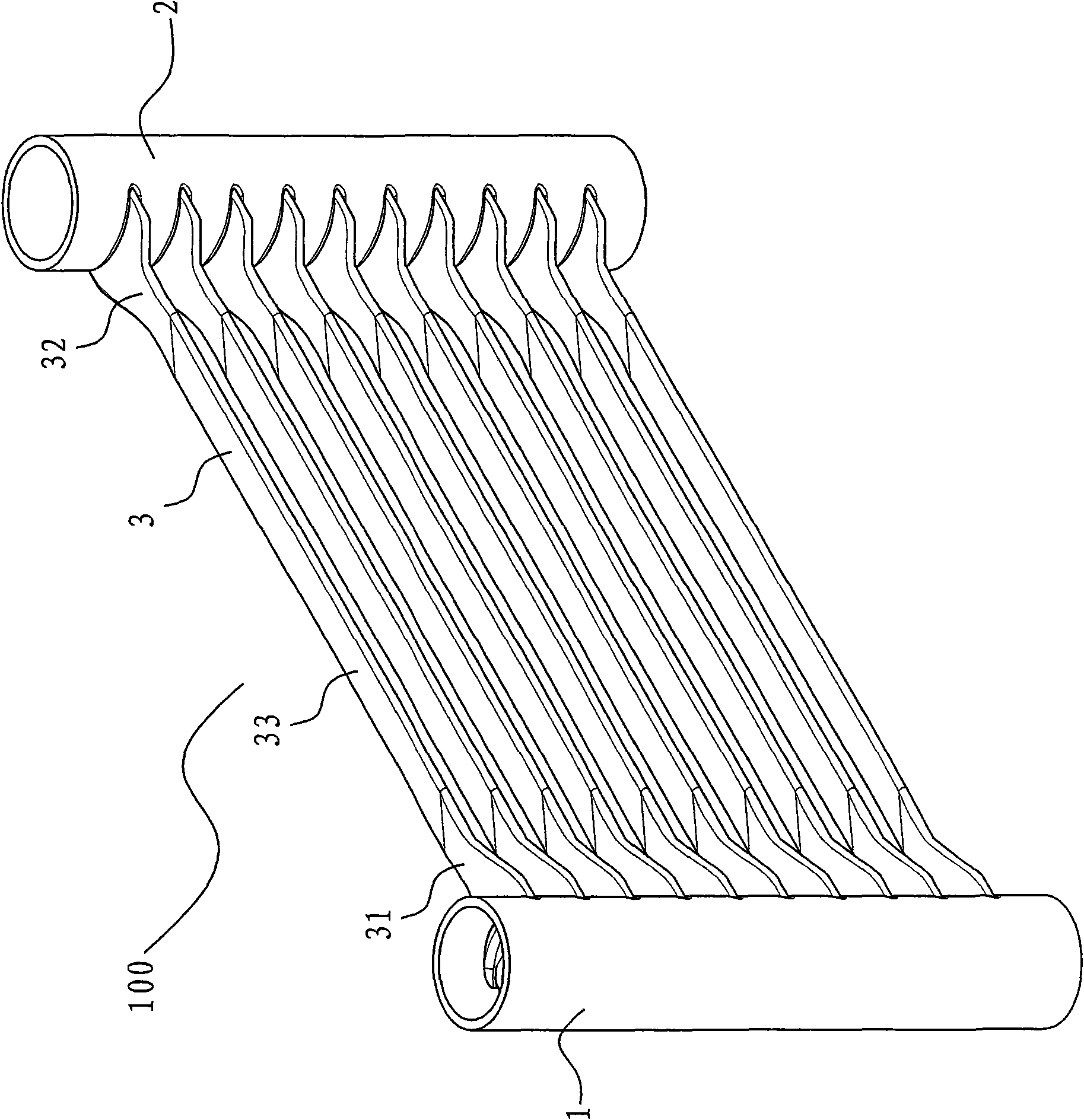
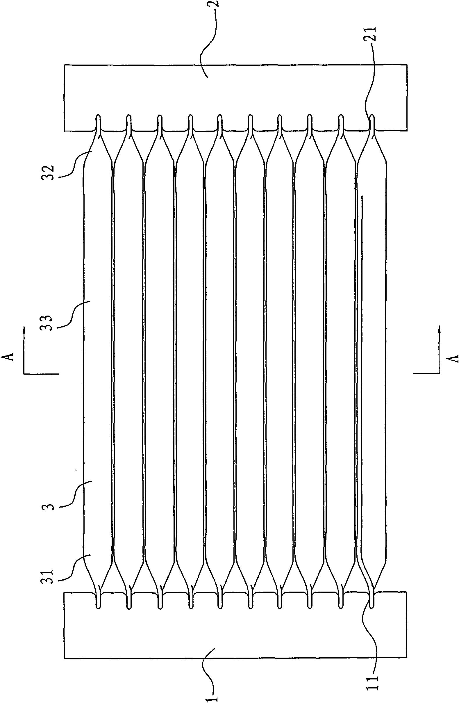
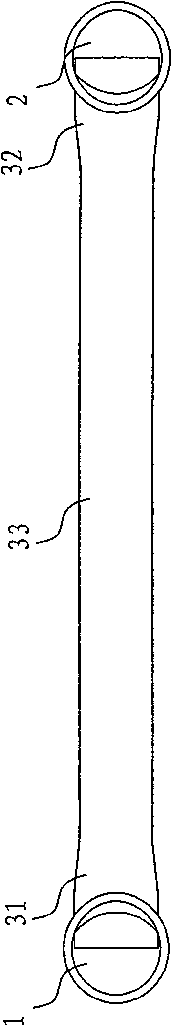
[0032] Refer below Figure 1-6 A heat exchanger 100 accordi...


PUM


Abstract

The invention discloses a heat exchanger which comprises a first collecting pipe, a second collecting pipe, a plurality of flat pipes and fins, wherein the second collecting pipe and the first collecting pipe are positioned in a first plane and spaced with a preset distance; the first end and the second end of each flat pipe are respectively connected with the first collecting pipe and the second collecting pipe so as to communicate the first collecting pipe and the second collecting pipe through fluid; an included angle between the plane of the flat pipes and a second plane being orthogonal to the first plane is alpha, wherein alpha is larger than 0 degree and smaller than 90 degrees; and the fins are arranged between adjacent flat pipes. When the heat exchanger is used as a single cooling evaporator or a heat pump type heat exchanger, condensed water flows downwards along inclined surfaces of the flat pipes or the fins under the action of self gravity to leave the surface of the heat exchanger and cannot be gathered on the flat pipes and the fins, thereby improving the draining effect and improving the heat exchange performance.

Description

technical field [0001] The present invention relates to a heat exchanger, in particular to a microchannel heat exchanger with improved drainage performance. Background technique [0002] The traditional parallel flow microchannel heat exchanger includes an inlet header, an outlet header, flat tubes arranged between the inlet header and the outlet header, and fins arranged between the flat tubes, wherein the flat tubes The top and bottom surfaces of the tubes are normal to the plane defined by the inlet and outlet headers. When the inlet and outlet headers are positioned vertically, the flat tubes are arranged horizontally between the inlet and outlet headers. [0003] When used as a cold-only evaporator or a heat pump heat exchanger, the above-mentioned traditional heat exchanger has deficiencies in drainage and thus in heat exchange performance. Specifically, due to the horizontal arrangement of the flat tubes, the condensed water on the fins will be blocked by the flat t...

Claims


Application Information

Patent Timeline
Patent Type & Authority Applications(China)
IPC IPC(8): F28D1/04F28F9/02F25B39/02
Inventor 刘华钊黄宁杰
Owner SANHUA HANGZHOU MICRO CHANNEL HEAT EXCHANGER
Why Eureka
Try Eureka