High-voltage power line carrier signal communication coupling method and device

A signal coupling, high-voltage power technology, applied in circuit devices, distribution line transmission systems, electrical components, etc., can solve the problems of complex installation, bulky, limited application of carrier communication technology, etc., and achieve cost reduction and cost savings. Effect

Inactive Publication Date: 2010-01-06
昆明天龙经纬电子科技有限公司
View PDF0 Cites 12 Cited by
  • Summary
  • Abstract
  • Description
  • Claims
  • Application Information

AI Technical Summary

Problems solved by technology

Low-voltage power line carrier communication technology has been widely used, but due to the limitation of high-voltage isolation coupling technology and cost, the application of carrier communication technology on 10kV and above lines is very limited
[0003] The current high-voltage carrier coupling almost uses a combination of high-voltage capacitors and combined filters for signal coupling. Since the carrier equipment is directly connected to the high-voltage line, it is necessary to solve the high-voltage technology, resulting in high equipment prices, bulky, complicated installation, and easy to cause lightning strikes. and other disadvantages
As a result, the application of power carrier communication of 10kV and above is restricted and cannot be popularized and applied

Method used


Image

  • High-voltage power line carrier signal communication coupling method and device
  • High-voltage power line carrier signal communication coupling method and device
  • High-voltage power line carrier signal communication coupling method and device

Examples


Embodiment Construction

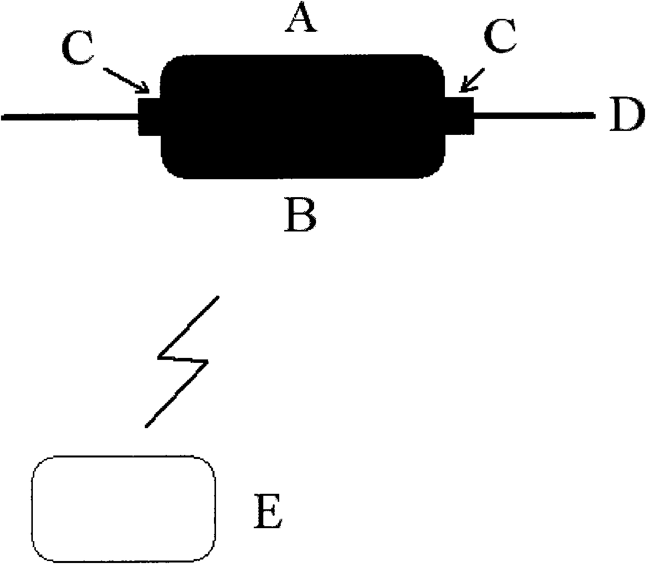
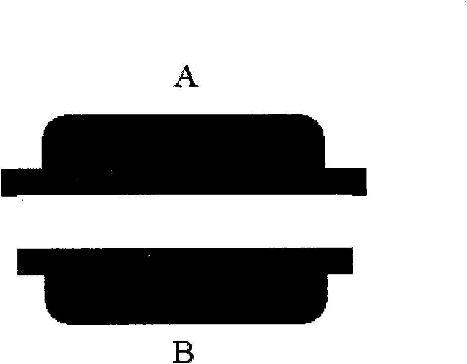
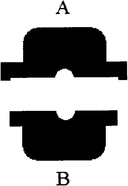
[0029] figure 1 As shown, it consists of coupling parts A and B installed on the high-voltage line and the ground interface part E for communication with the upper and lower halves. Parts A and B are clamped on the high-voltage line D by fastening screws C. Parts A and B adopt waterproof structure, see figure 2 , image 3 .

[0030] Its power supply of the described device is taken from the current transformer synthesized by two semicircular rings, see Figure 4 1 and 4, the upper part 1 of the semi-circular transformer core is wound with a coil, see Figure 10 As shown in CT1, it can sense the current in the high-voltage transmission line. Due to the saturated iron core, no overcurrent will be generated; the current generated in the coil is transformed into a 15V working power supply by constant current.

[0031] The coupling of the carrier signal of the device is completed by the carrier transformer synthesized by two semi-circular rings, see Figure 4 3 and 5, the hig...


PUM


Abstract

The invention relates to a high-voltage power line carrier signal communication coupling method and a device. The device comprises two groups of semi-annular transformers, wherein one group is current transformers, and the other group is carrier transformers; each group is divided into an upper half part and a lower half part which are respectively arranged in the upper casing and the lower casing of a high-voltage transmission line; and two semi-annular transformers in the upper casing are respectively wound by coils which are connected with a circuit board arranged at the upper side. When the upper casing provided with the two semi-annular transformers is combined with the lower casing provided with two semi-annular transformers to clamp on the high-voltage power line, the transformers are respectively form complete current transformers and carrier transformers; the high-voltage line penetrates through the center of a magnetic circuit to generate electric current which is used for supplying power for equipment after being converted; and the carrier transformers are used for coupling carrier signals to the high-voltage power line or inducing carrier signals from the high-voltage power line, and the carrier signals are transmitted to ground equipment in a wireless mode. The invention solves the problem of difficult insulation and isolation between the ground equipment and the high-voltage power line, realizes remote meter-reading at low voltage, and saves cost.

Description

technical field [0001] The invention relates to a method and a device for coupling a carrier signal to a high-voltage transmission line. Background technique [0002] With the improvement of power grid management requirements, the requirements for remote power data collection are becoming more and more urgent. Low-voltage power line carrier communication technology has been widely used, but due to the technical and cost constraints of high-voltage isolation coupling, the application of carrier communication technology on 10kV and above lines is very limited. [0003] The current high-voltage carrier coupling almost uses a combination of high-voltage capacitors and combined filters for signal coupling. Since the carrier equipment is directly connected to the high-voltage line, it is necessary to solve the high-voltage technology, resulting in high equipment prices, bulky, complicated installation, and easy to cause lightning strikes. and other disadvantages. As a result, th...

Claims


Application Information

Patent Timeline
Patent Type & Authority Applications(China)
IPC IPC(8): H04B3/56H02J13/00
CPCY02E60/7892Y02E60/7823Y04S40/146Y04S40/122Y02E60/00Y04S40/126
Inventor 张龙
Owner 昆明天龙经纬电子科技有限公司
Why Eureka
Try Eureka