

Resource determining method of special demodulation data reference signal
A technology for demodulating data and reference signals, which is applied in the field of reference signals in mobile communications, and can solve problems such as undetermined multiplexing methods
- Summary
- Abstract
- Description
- Claims
- Application Information
AI Technical Summary
Problems solved by technology
Method used
Image

Examples
no. 1 example
[0156] In this embodiment, the number of layers is divided into two categories, the total number of layers being 1 or 2 is the first category, and the total number of layers is greater than 2 is the second category.
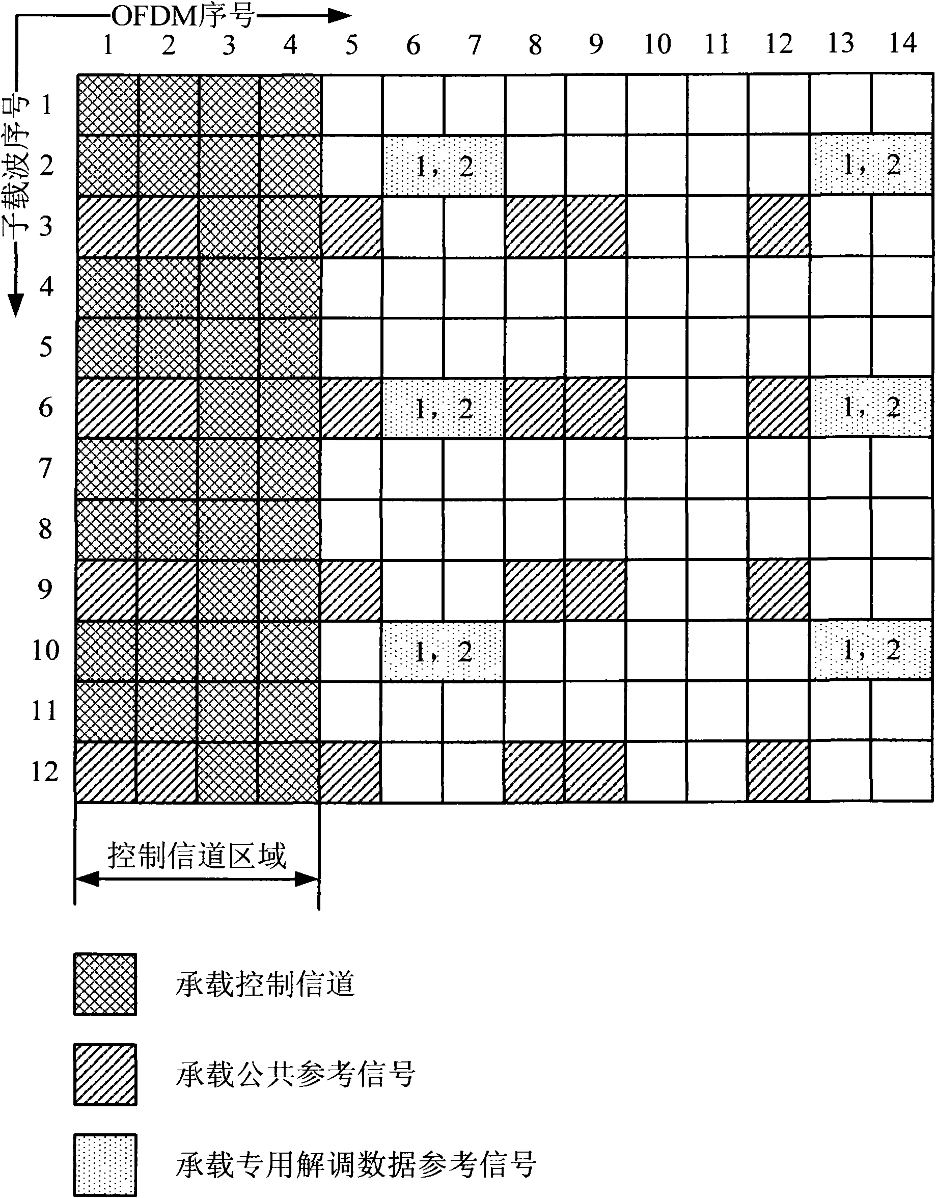
[0157] FIG. 2(A) is a schematic diagram of the location of the first type of dedicated demodulation data reference signal in an RB. As shown in Figure 2(A), all dedicated demodulation data reference signals in the first category occupy 12 REs in one RB, and the positions of these 12 REs in one RB can be expressed in the form of coordinates (x, y) Expressed as:
[0158] (6,2) (7,2) (13,2) (14,2)
[0159] (6,6) (7,6) (13,6) (14,6)
[0160] (6,10) (7,10) (13,10) (14,10);
[0161] Wherein, x represents an OFDM symbol index in one RB, and y represents a subcarrier index in one RB. In the following embodiments, unless otherwise specified, the position of the RE in the RB is expressed in the form of coordinates (x, y).
[0162] Alternatively, the position of the fi...
no. 2 example
[0200] According to the number of layers, it is divided into 2 categories. The total number of layers is 1 or 2 for the first category, and the total number of layers is greater than 2 for the second category.
[0201] FIG. 3(A) is a schematic diagram of the location of the first type of dedicated demodulation data reference signal in the RB. As shown in Figure 3(A), all dedicated demodulation data reference signals in the first category occupy 12 REs in one RB, and the positions of these 12 REs in one RB can be expressed in the form of coordinates (x, y) Expressed as:
[0202] (6,1) (7,1) (13,1) (14,1)
[0203] (6,6) (7,6) (13,6) (14,6)
[0204] (6, 11) (7, 11) (13, 11) (14, 11).
[0205] Alternatively, the position of the first type of dedicated demodulation data reference signal in one RB can also be expressed as:
[0206] The first subcarriers of the sixth, seventh, thirteenth and fourteenth OFDM symbols;
[0207] the sixth subcarrier of the sixth, seventh, thirteenth...
no. 3 example
[0241] According to the number of layers, it is divided into 2 categories. The total number of layers is 1 or 2 for the first category, and the total number of layers is greater than 2 for the second category.
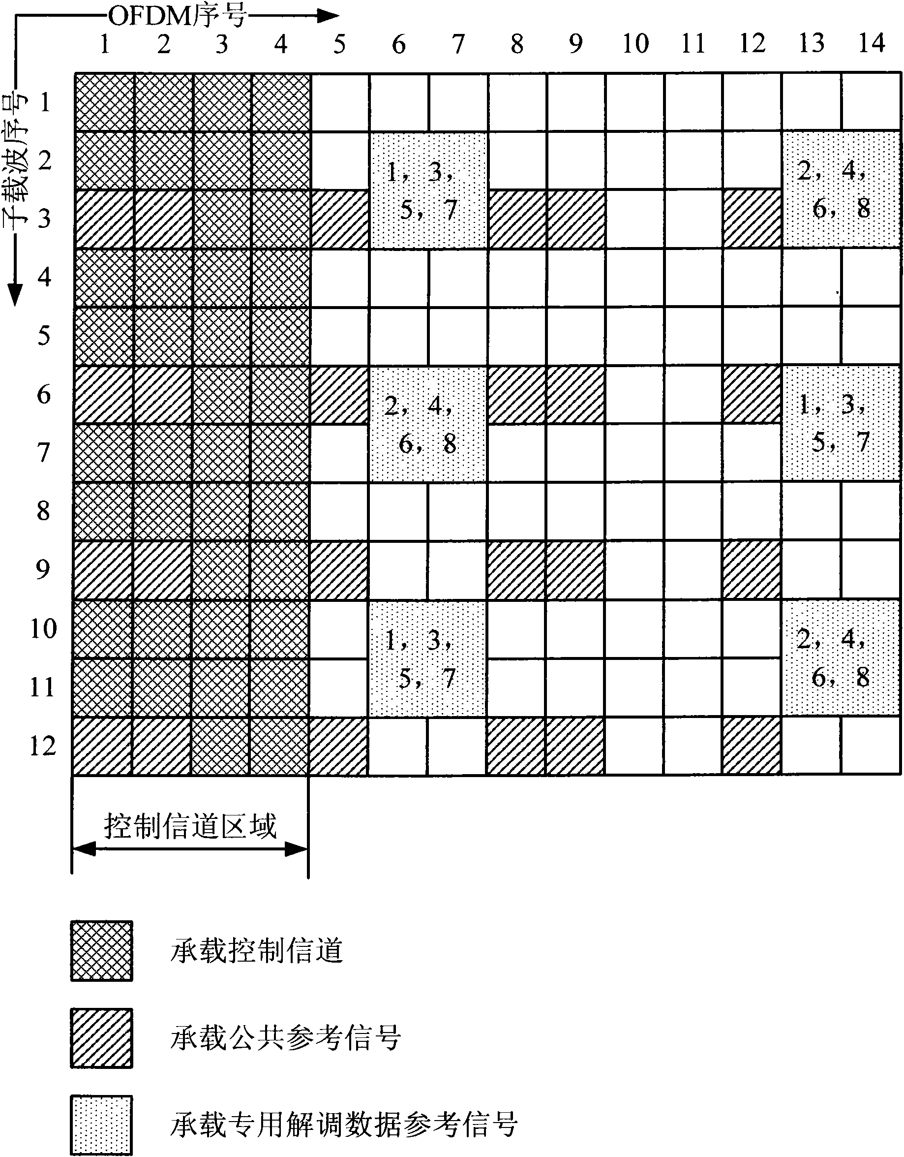
[0242]FIG. 4(A) is a schematic diagram of the location of the first type of dedicated demodulation data reference signal in the RB. As shown in Figure 4(A), all dedicated demodulation data reference signals in the first category occupy 12 REs in one RB, and the positions of these 12 REs in one RB can be expressed in the form of coordinates (x, y) Expressed as:
[0243] (6,2) (7,2) (13,2) (14,2)
[0244] (6,6) (7,6) (13,6) (14,6)
[0245] (6,10) (7,10) (13,10) (14,10);
[0246] Alternatively, the position of the first type of dedicated demodulation data reference signal in one RB can also be expressed as:
[0247] The second subcarrier of the sixth, seventh, thirteenth and fourteenth OFDM symbols;
[0248] the sixth subcarrier of the sixth, seventh, thirteenth and ...
PUM
 Abstract
Description
Claims
Application Information