Field piece
A technology of excitation system and magnetic body, applied in the direction of magnetic circuit, magnetic circuit rotating parts, magnetic circuit shape/style/structure, etc. effect of noise
- Summary
- Abstract
- Description
- Claims
- Application Information
AI Technical Summary
Problems solved by technology
Method used
Image
Examples
no. 1 Embodiment approach
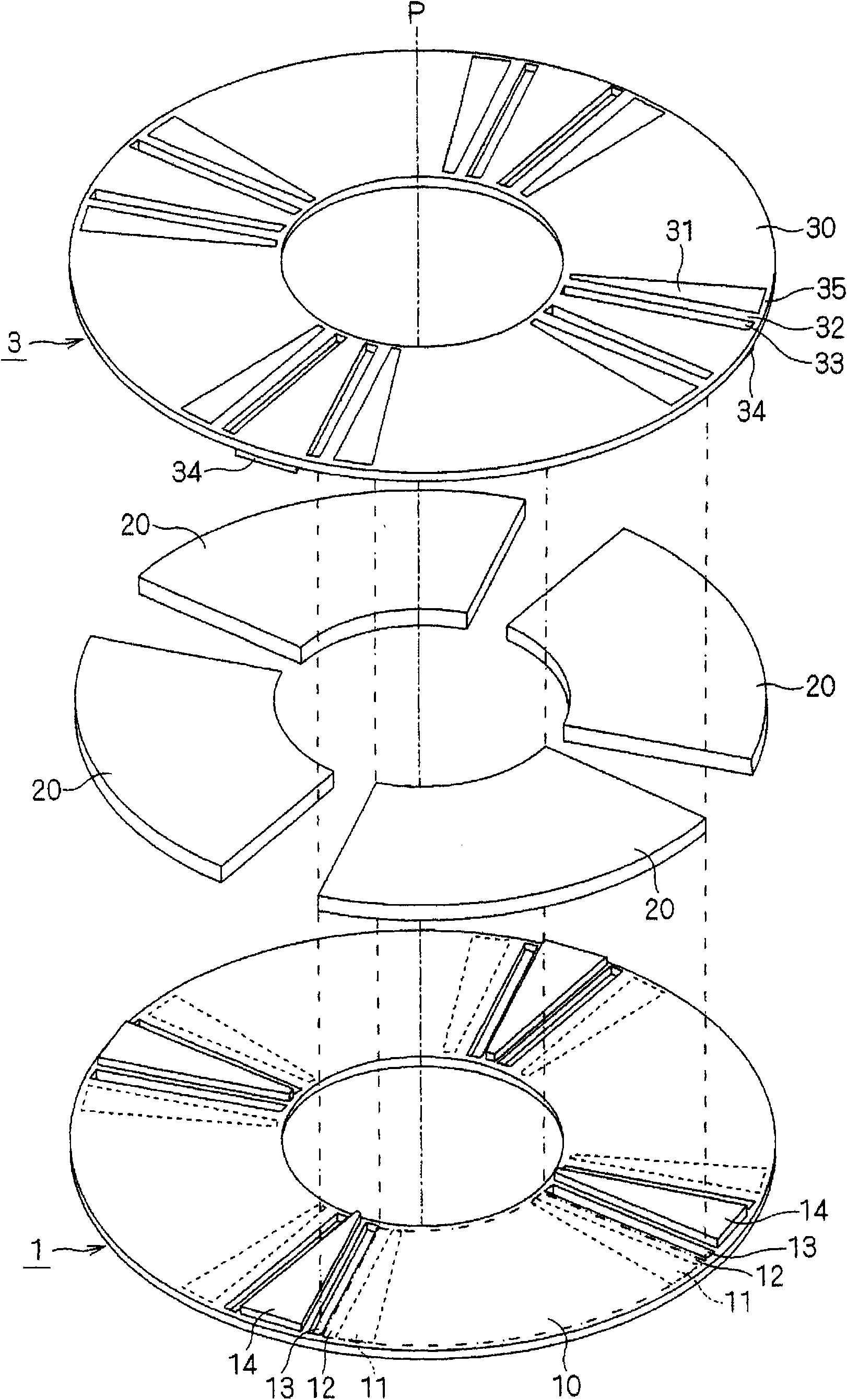
[0059] The excitation system of the first embodiment of the present invention will be described. figure 1 It is a schematic perspective view obtained by decomposing the excitation system along the rotation axis P. figure 1 The excitation system shown is a so-called axial-gap excitation system.
[0060] The excitation system has permanent magnets 20 and magnetic plates 1 , 3 .
[0061] The permanent magnet 20 is magnetized in a direction parallel to the rotation axis P (hereinafter referred to as the rotation axis direction). The permanent magnet 20 is arranged in a ring shape, and its magnetization direction is alternately changed around the rotation axis P. As shown in FIG. exist figure 1 A so-called 4-pole excitation system configured with four permanent magnets 20 is exemplified in .
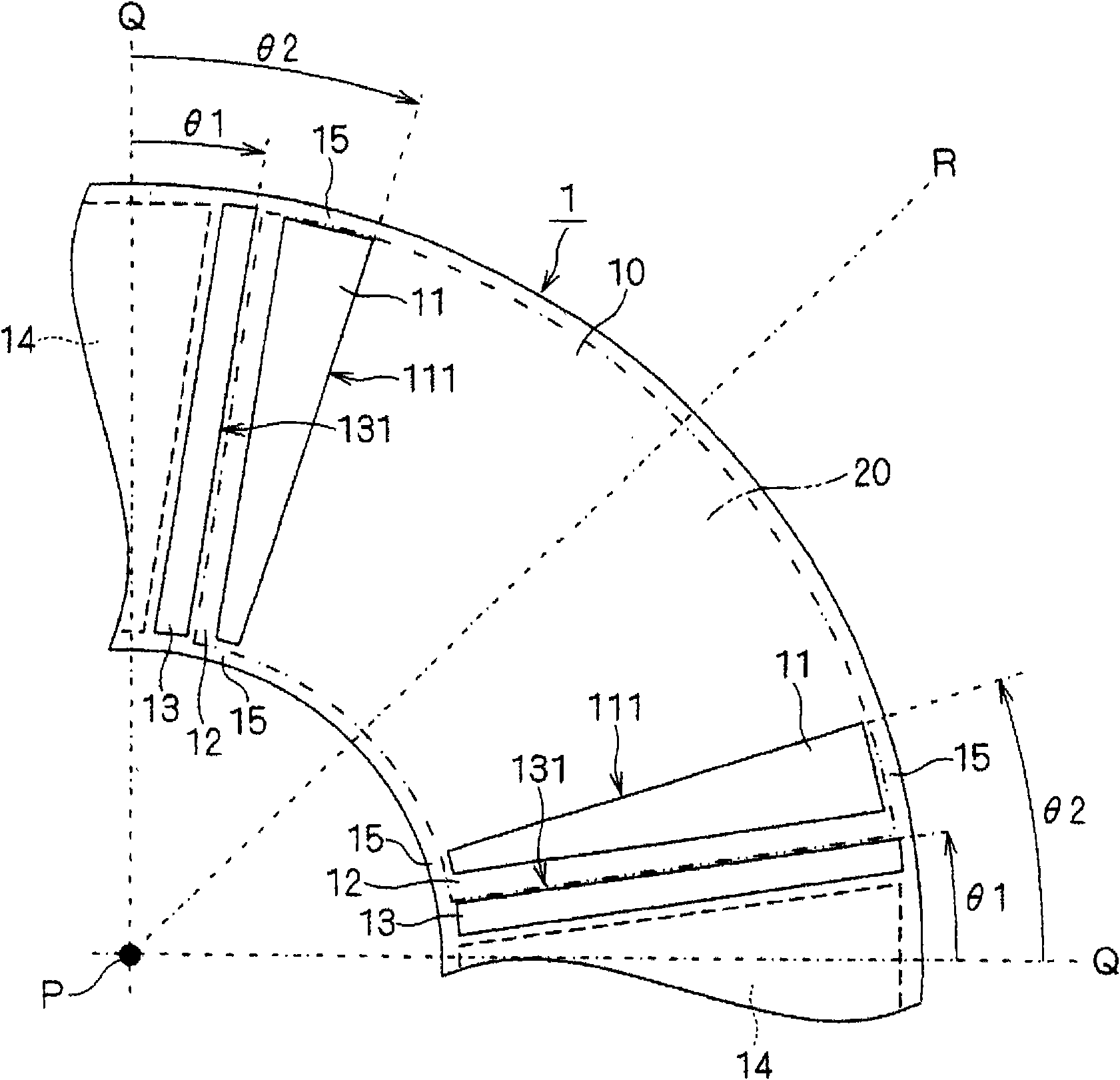
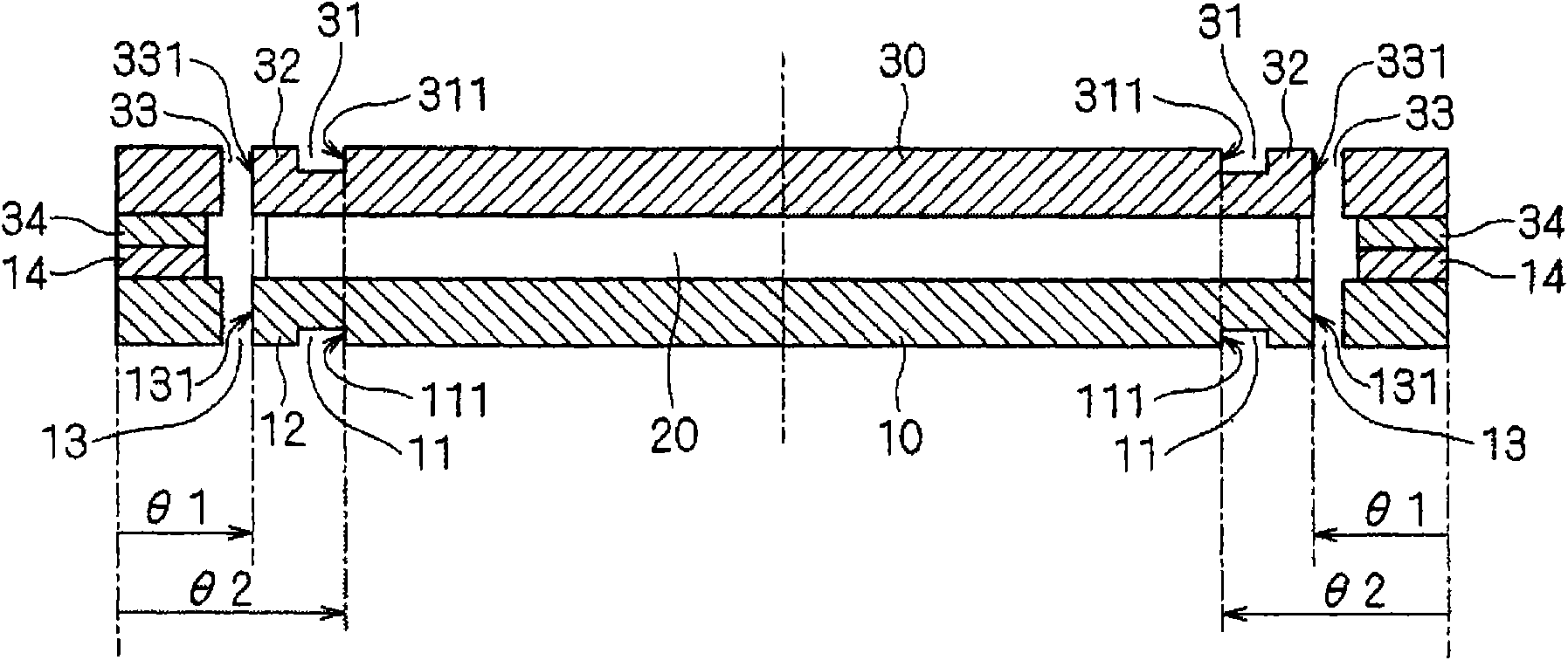
[0062] The magnetic plates 1 and 3 have, for example, an annular flat plate shape centered on the rotation axis P. As shown in FIG. Magnetic body 1,3 and permanent magnet 20 are in figu...
no. 2 Embodiment approach
[0101] An excitation system according to a second embodiment of the present invention will be described by describing differences from the first embodiment. Figure 8 is a schematic bottom view of the excitation system. Figure 9 yes Figure 8 A cross-sectional view of the shown excitation system in the circumferential direction, at the positions where the non-magnetic bodies 11 and 13 are located. exist Figure 8 , 9 A part corresponding to one permanent magnet 20 is shown in .
[0102] The nonmagnetic body 11 has nonmagnetic body parts 11a and 11b, and the nonmagnetic body 13 has nonmagnetic body parts 13a and 13b. The nonmagnetic body 31 has nonmagnetic body parts 31a, 31b, and the nonmagnetic body 33 has nonmagnetic body parts 33a, 33b. Next, first, the case where the magnetic plates 1 and 3 have the same shape as each other will be described.
[0103]The non-magnetic body portion 11a is, for example, an air layer. The non-magnetic body portion 11b is, for example, ...
no. 3 Embodiment approach
[0131] An excitation system according to a third embodiment of the present invention will be described by describing differences from the second embodiment. Figure 10 The part corresponding to one permanent magnet 20 in the bottom view of this excitation system is shown. in addition, Figure 10 The schematic cross-sectional view of the circumferential direction of the shown excitation system, the position where the non-magnetic bodies 11, 13 are located and image 3 Much the same.
[0132] The lengths of the non-magnetic body parts 11a and 11b in the radial direction (hereinafter simply referred to as lengths) are different from each other. Specifically, the length of the nonmagnetic body part 11b is shorter than the length of the nonmagnetic body part 11a. In addition, the thicknesses of the non-magnetic body parts 11a and 11b are the same as each other.
[0133] The lengths of the non-magnetic body parts 13a and 13b are different from each other. Specifically, the leng...
PUM
 Abstract
Description
Claims
Application Information
 - R&D
- Intellectual Property
- Life Sciences
- Materials
- Tech Scout
- Unparalleled Data Quality
- Higher Quality Content
- 60% Fewer Hallucinations
Browse by: Latest US Patents, China's latest patents, Technical Efficacy Thesaurus, Application Domain, Technology Topic, Popular Technical Reports.
© 2025 PatSnap. All rights reserved.Legal|Privacy policy|Modern Slavery Act Transparency Statement|Sitemap|About US| Contact US: help@patsnap.com


