Image encoding and image decoding method and device

An image coding and image decoding technology, applied in image communication, television, electrical components, etc., can solve problems such as impossible quantization processing optimization

Inactive Publication Date: 2010-01-06
KK TOSHIBA
View PDF2 Cites 22 Cited by
  • Summary
  • Abstract
  • Description
  • Claims
  • Application Information

AI Technical Summary

Problems solved by technology

However, in JP-A 2003-189308, as in Document 1, it is also impossible to optimize the quantization process in units of quantization blocks.

Method used


Image

  • Image encoding and image decoding method and device
  • Image encoding and image decoding method and device
  • Image encoding and image decoding method and device

Examples


no. 1 approach

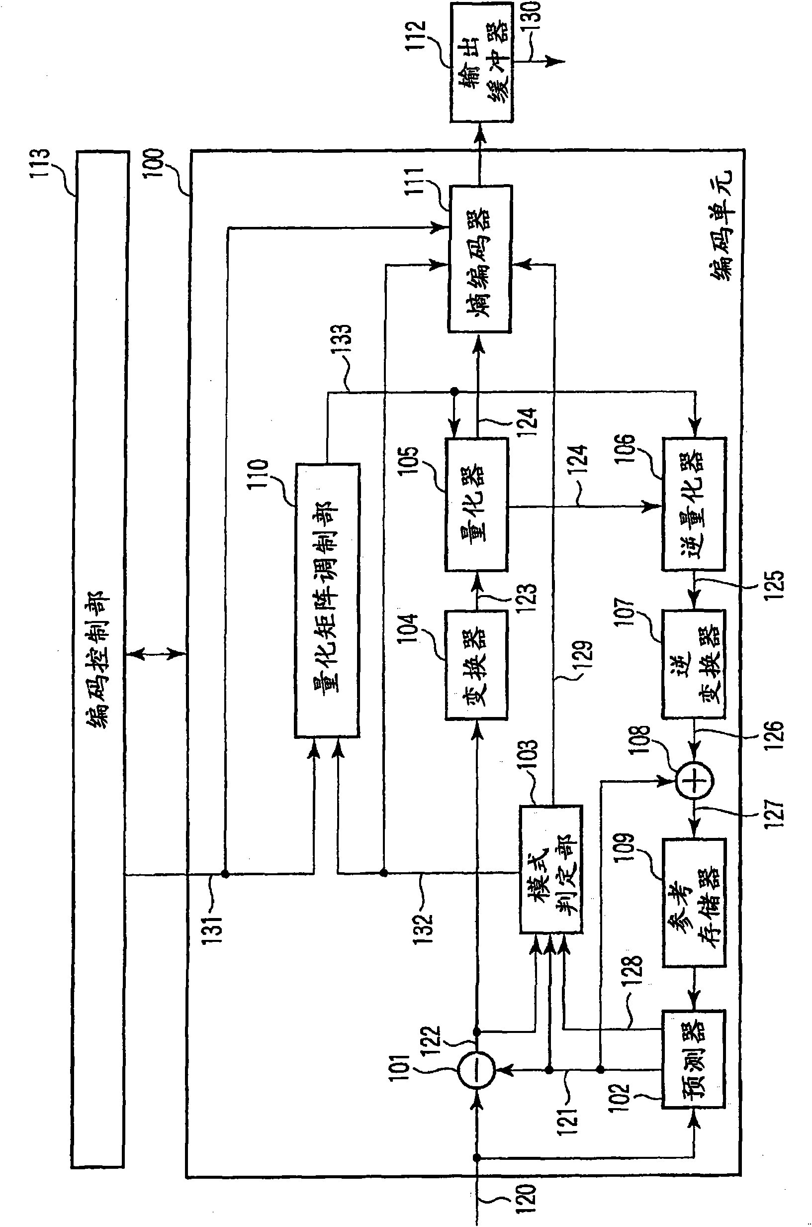
[0051] refer to figure 1 In the image encoding device according to the first embodiment of the present invention, an input image signal 120 of a moving image or a still image is divided into small pixel block units, such as macroblock units, and input to the encoding section 100 . Here, a macroblock is used as a basic processing block size (size) of encoding processing. Hereinafter, the encoding target macroblock of the input image signal 120 is simply referred to as a target block.

[0052]Coding section 100 prepares a plurality of prediction modes that differ in block size or method of generating a predicted image signal. Specifically, methods for generating a predicted image signal are broadly classified into intra prediction in which a predicted image is generated only within a frame to be coded, and inter prediction in which prediction is performed using a plurality of temporally different reference frames. In this embodiment, for simplicity of description, as figure ...

no. 2 approach

[0191] When the quantizer 105 and the inverse quantizer 106 perform quantization / inverse quantization corresponding to Equation (6) and Equation (18), instead of modulating the quantization matrix as in the first embodiment, it is also possible to control the quantization / inverse quantization Operation accuracy is modulated by the operation accuracy control parameter. In this case, Formula (6) and Formula (18) are respectively changed as follows.

[0192] Y(i,j)=sign(X(i,j))×(abs(X(i,j))×QM(i,j)×MLS(i,j,idx)+f)>>Q bit

[0193] (26)

[0194] X'(i,j)=sign(Y(i,j))×(abs(Y(i,j))×QM(i,j)×IMLS(i,j,idx))bit

[0195] (27)

[0196] Here, MLS and IMLS are modulated calculation accuracy control parameters and are expressed by the following equation.

[0197] MLS(i j, idx) = (LS(i, j) + MM(i, j, idx)) (28)

[0198] IMLS(i, j, idx) = (ILS(i, j...

no. 3 approach

[0205] When the quantizer 105 and the inverse quantizer 106 perform quantization / inverse quantization corresponding to Equation (4) and Equation (16), instead of modulating the quantization matrix as in the first embodiment, the quantization parameter may be modulated. In this case, Formula (4) and Formula (16) are respectively changed as follows.

[0206] Y(i,j)=sign(X(i,j))×(abs(X(i,j))×QM(i,j)×LS(i,j)+f) / (QP step (i, j, idx))

[0207] (30)

[0208] X'(i,j)=sign(Y(i,j))×(abs(Y(i,j))×QM(i,j)×ILS(i,j))×(QP step (i, j, idx))

[0209] (31)

[0210] Here, QP step is the modulation quantization parameter, expressed by the following formula.

[0211] QP step (i, j, idx) = (Q step +MM(i, j, idx)) (32)

[0212] Here, Q step is the quantization parameter.

[0213] So for the quantization parameter Q step Modulating has the ...


PUM


Abstract

An image encoding device includes: a predictor which predicts an input image signal and generates a predicted image signal; a subtractor which calculates a difference between the input image signal and the predicted image signal to generate a predicted residual signal; a converter which converts the predicted residual signal to generate a conversion coefficient; a modulation unit which modulates a quantization matrix to obtain a modulated quantization matrix; a quantizer which quantizes the conversion coefficient by using the modulated quantization matrix to generate a quantized conversion coefficient; and an encoder which encodes the quantized conversion coefficient and the modulation index to generate encoded data.

Description

technical field [0001] The present invention relates to methods and devices for image coding and image decoding of moving images or still images. Background technique [0002] In recent years, an image coding method that greatly improves coding efficiency has been jointly proposed by ITU-T and ISO / IEC as ITU-T Rec. H.264 and ISO / IEC 14496-10 (hereinafter referred to as H.264). Coding methods such as ISO / IEC MPEG-1, 2 and 4, ITU-T H.261 and H.263 use 2D DCT of 8×8 blocks for compression. In contrast, since H.264 uses a 4×4 block two-dimensional integer orthogonal transformation, it is not necessary to consider IDCT mismatch, and operations based on 16-bit registers can be realized. [0003] Furthermore, in H.264 High Profile, as a tool for subjective image quality improvement for high-resolution images such as HDTV size (size), a quantization matrix is ​​introduced for quantization processing of orthogonal transform coefficients (Refer to J. Lu, "Proposal of quantization we...

Claims


Application Information

Patent Timeline
Patent Type & Authority Applications(China)
IPC IPC(8): H04N7/50
CPCH04N19/00781H04N19/00278H04N7/26319H04N7/26313H04N7/26244H04N19/00096H04N7/26154H04N7/50H04N7/26308H04N19/00351H04N19/00545H04N19/00357H04N7/26085H04N19/00175H04N19/126H04N19/147H04N19/157H04N19/176H04N19/18H04N19/19H04N19/192H04N19/61H04N19/70H04N19/124H04N19/51
Inventor 谷泽昭行中条健
Owner KK TOSHIBA
Why Eureka
Try Eureka