Strong impaction lock core of anti-bump key

A lock cylinder and anti-collision technology, applied in the field of locks, can solve the problems of many marbles and troublesome installation, and achieve the effect of ensuring the anti-collision key function and strengthening the safety function.

Inactive Publication Date: 2010-01-13
郑力仁
View PDF1 Cites 2 Cited by
  • Summary
  • Abstract
  • Description
  • Claims
  • Application Information

AI Technical Summary

Problems solved by technology

"However, there are many pins to be changed in the lock cylinder of this u

Method used


Image

  • Strong impaction lock core of anti-bump key
  • Strong impaction lock core of anti-bump key
  • Strong impaction lock core of anti-bump key

Examples


Embodiment 1

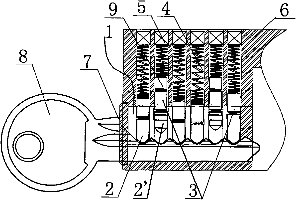
[0024] An Anti-bumping lock cylinder (Anti-bumping lock cylinder), including a lock cylinder inner core (lock cylinder barrel or plug) 1 ( figure 1 ), the lock cylinder body (lock cylinder housing) 6, the six columns of cylindrical pinholes that are connected to the lock cylinder inner core and the lock cylinder body, the lower pinhole 2 in the pinholes of the lock cylinder inner core, the pinholes of the lock cylinder body The top pin 5 for sealing the door, the spring 4 below the pin for closing the door, the upper pin 3 in the pin hole of the lock core body when the lock core is open, and the key hole 7; it is characterized in that the lock core in the six rows of pin holes There are two rows of lower marbles arranged in the pin hole of the core, which are anti-collision key pins (lock cylinder housing) 2', and the anti-collision key pins are suspended in the pin hole of the inner core 1 of the lock cylinder. > the diameter of the lower marble 2, the diameters of its upper ...

Embodiment 2

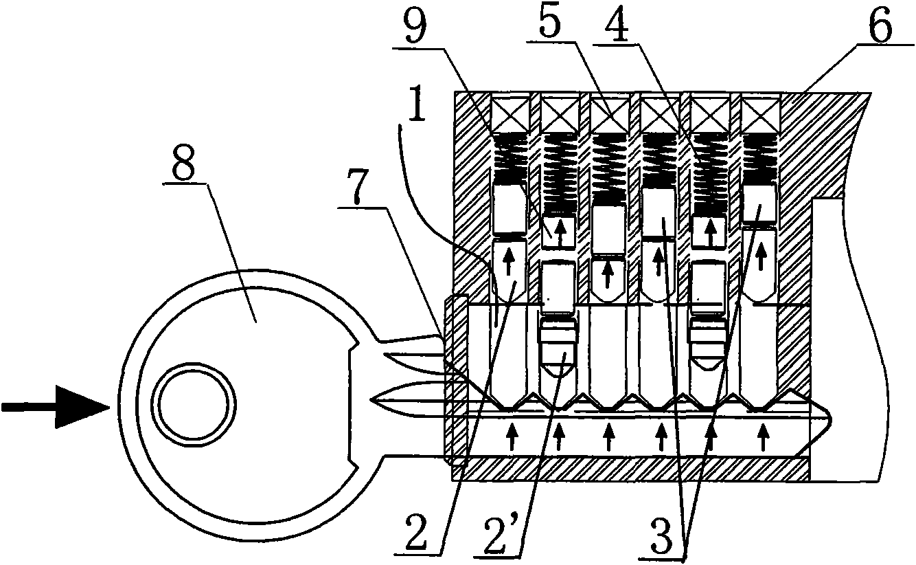
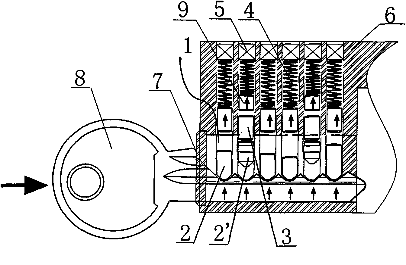
[0032] Embodiment 2 is substantially the same as Embodiment 1 ( Figure 5-7 ). The difference is: in embodiment 2, the cylindrical thin marble is arranged under the upper marble 3 in the pin hole, on the anti-collision key marble 2 ', that is, between the anti-collision key marble 2 ' and the upper marble 3 ( Figure 5 , 6 , 7). The thickness of the cylindrical thin marble is greater than the distance from the top of the anti-collision key marble 2' to the top of the inner core of the lock cylinder.

[0033] The same principle, such as, Image 6 , although the upper and lower pins in the 1st, 3rd, 4th, and 6th columns are knocked out of the pin holes in the inner core of the lock cylinder, but the cylindrical thin pins in the 2nd and 5th columns are stuck in the lock cylinder Between the pin hole of the core and the pin hole of the lock core body, the inner core of the lock core cannot be rotated, and the lock cannot be opened. Another example, Figure 7 , although the u...


PUM


Abstract

The invention discloses a strong impaction lock core of an anti-bump key, which comprises a lock inner core and a lock core body, a plurality of lines of marble holes communicated mutually and arranged on the lock inner core and the lock core body, lower marbles in the marble holes of the lock inner core, a closed marble at the top of the marble hole of the lock core body, a spring at the lower side of the closed marble, upper marbles and a key hole. The strong impaction lock core is characterized in that at least more than one line of lower marbles arranged in the marble holes of the lock inner cores in the marble holes are anti-bump key marbles which are hung in the marble holes of the lock inner core, the diameter of the middle part of the anti-bump key marbles is larger than the diameter of the lower marbles, the diameters of the upper part and the lower part are larger than or equal to the diameter of the lower marbles and are less than the diameter of the middle part, the upper edges of the anti-bump key marbles are lower than the upper plane of the lock inner core, and the lower edges of the anti-bump key marbles are higher than the bottoms of the marble holes of the lock inner core. The marble holes of the lock inner core are internally provided with the anti-bump key marbles, and a cylindrical thin marble is arranged under the spring. The lock core can by strongly impacted by the anti-bump key.

Description

technical field [0001] The invention relates to the field of locks, in particular to a mechanical tumbler lock cylinder with the function of anti-crash key tampering. In particular, it is a mechanical tumbler lock cylinder with the function of preventing a strike key from being struck by a strong force to implement tampering. Background technique [0002] Nowadays, it is popular to use a bump key (Bump key in English) to unlock, also known as "999" key to unlock. The principle is to open the teeth of the key to the maximum, and after the bump key is inserted into the key hole, the lower marbles in the inner core of the lock cylinder will touch the roots of the teeth of the bump key. Then, strike the rear of the striker. At this time, due to the principle of action force and reaction force, the bump key knocks the upper pin in the pins of the inner core of the lock cylinder out of the pin hole in the inner core of the lock core. Turn the lock cylinder to achieve the purpos...

Claims


Application Information

Patent Timeline
IPC IPC(8): E05B15/00E05B27/04
Inventor 郑力仁程辉
Owner 郑力仁
Why Eureka
Try Eureka