
Light emitting diode lighting device

A technology of light-emitting diodes and lighting, which is applied to lighting devices, components of lighting devices, lighting and heating equipment, etc. It can solve the problems of affecting the efficiency of lighting devices, processing difficulties, uneconomical principles, energy saving and carbon reduction needs, etc. question

Inactive Publication Date: 2010-01-13
CREATE ELECTRONICS OPTICAL
View PDF0 Cites 12 Cited by
  • Summary
  • Abstract
  • Description
  • Claims
  • Application Information

AI Technical Summary

Problems solved by technology

[0004] In the current application technology that uses light-emitting diodes (LEDs) as light sources, such as lighting devices such as flashlights, desk lamps, car lights, headlights and taillights, street lights, etc., because light-emitting diodes (LEDs) and related circuits Accessories (such as the circuit board used to hold the LED) must have a waterproof function to avoid damage, so most of the LED and its second lens will be provided with a lampshade (outer cover) to achieve waterproof protection; however, due to The volume of the lampshade (cover) is generally large, such as the lampshade (cover) of a common outdoor street lamp. Therefore, if the lampshade (cover) is directly made of optical glass or optical plastic material, it is not only economical and energy-saving. Carbon reduction needs, and the processing is quite difficult and difficult to effectively control; and if the lampshade (cover) is made of ordinary glass or plastic materials, the LED light must at least pass through the second lens and the back of the lampshade (cover) Only when it is projected outward again, the process loss is relatively increased at this time (the light loss of general glass or plastic materials is about 8-15%), and the effective illuminance is relatively reduced, which seriously affects the use efficiency of the lighting device.

Method used


Image

  • Light emitting diode lighting device
  • Light emitting diode lighting device
  • Light emitting diode lighting device

Examples


Embodiment Construction

[0016] The above and other technical features and advantages of the present invention will be described in more detail below in conjunction with the accompanying drawings.

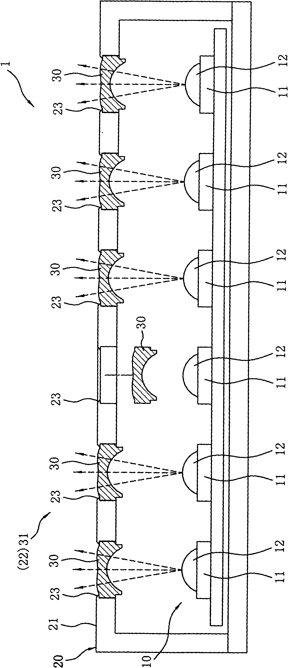
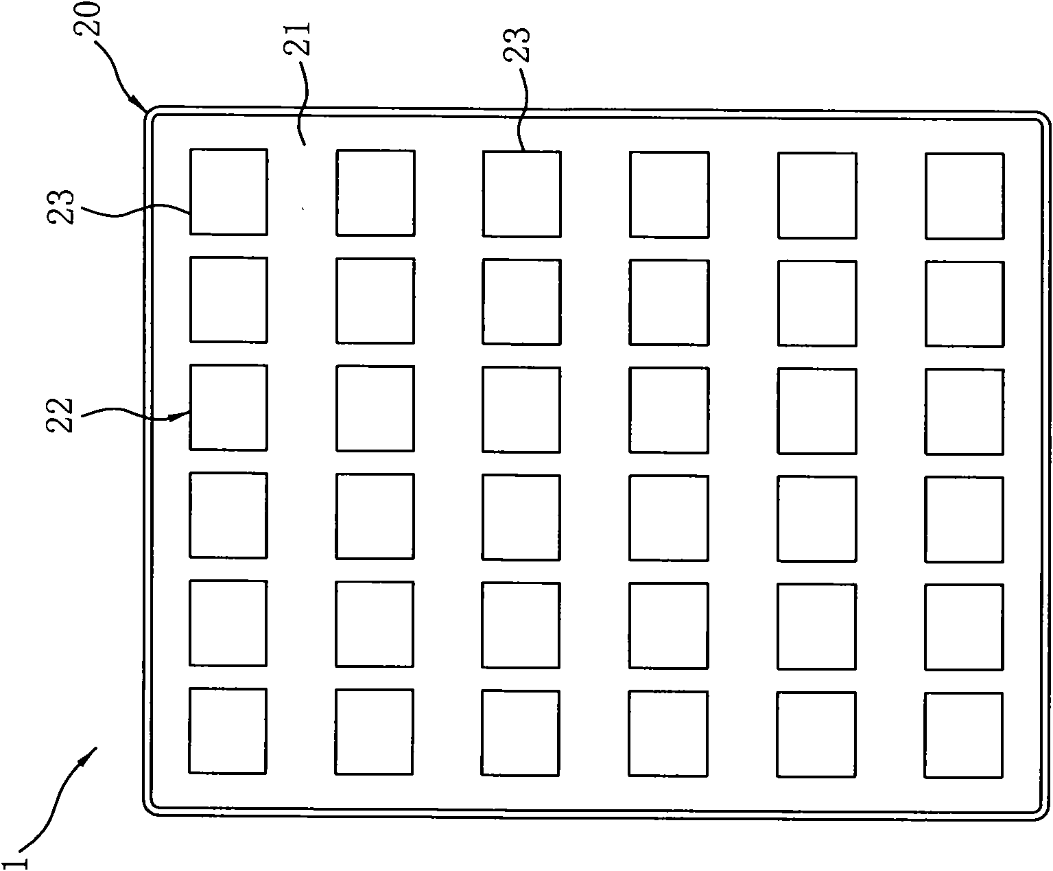
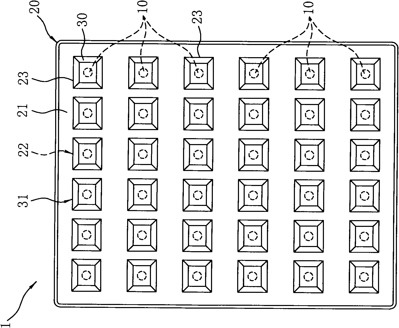
[0017] refer to Figure 1 to Figure 3 , which are respectively a side sectional view of an embodiment of the LED lighting device of the present invention and a schematic top view of the second lens not yet embedded or embedded on the outer cover. The present invention is a light-emitting diode (light-emitting diode, referred to as LED) lighting device 1, which mainly includes an LED array (array) 10 and a cover (holder) 20; wherein, the shape of the LED lighting device 1, The assembly type and size are not limited, and can be designed according to different needs in the application field, such as flashlights, table lamps, car lights, headlights and taillights, street lights, or auxiliary lighting devices for other electronic products such as cameras Different designs are provided for different application...


PUM


Abstract

The invention discloses a light emitting diode (LED) lighting device, which comprises a light emitting diode (LED) array and an external holder. The LED array is formed by arraying a plurality of light emitting diodes (LED) in a certain pattern; and the external holder is hermetically covered on the front periphery of the LED array, prevents water and protects the LED array. A hole slot array is arranged on a corresponding plate surface of the external holder facing the LED array. A plurality of 2nd lenses used together with the LEDs are correspondingly embedded in hole slots of the hole slot array respectively and are combined with the hole slot array to form a second lens array so as to outwards project the LED light generated by the LED array by the second lens array. The lighting device has multiple functions of reducing loss in the use process, improving effective illumination level, simplifying assembly, improving optical efficiency, enhancing availability factor and the like.

Description

technical field [0001] The invention relates to a lighting device, in particular to a light emitting diode (LED) lighting device. Background technique [0002] The use of light-emitting diodes (light-emitting diodes, referred to as LED) as the light source of lighting devices is an existing technology, and the application fields are quite extensive, such as flashlights, table lamps, car lights, headlights and taillights, street lights, or other Auxiliary lighting devices for electronic products, such as camera flashes, scanning lighting light source devices, etc., mostly use a plurality of light-emitting diodes (LEDs) to form an array as a light source, and the above-mentioned LED array refers to a plurality of LEDs according to the needs of the lighting device. And arranged in a certain pattern (pattern), such as linear arrangement, matrix arrangement, concentric circular arrangement, etc., but not limited to the above-mentioned arrangement; and a light-emitting diode (LED)...

Claims


Application Information

Patent Timeline
IPC IPC(8): F21S2/00F21V3/02F21V5/04F21Y101/02F21Y105/00F21K9/20F21K9/66F21K9/69F21V19/00F21Y115/10
Inventor 罗智玮徐运强朱翊麟
Owner CREATE ELECTRONICS OPTICAL
Learn More