
Method for monitoring memory in real time by embedded system

An embedded system, real-time monitoring technology, applied in resource allocation, multi-program device, software testing/debugging, etc., can solve problems such as lack of timeliness, inability to report immediately, and increased difficulty of debugging, so as to save development manpower costs , speed up the elimination speed, and improve the effect of software quality

Inactive Publication Date: 2010-01-13
WUDI SCI & TECH (XIAN) CO LTD
View PDF0 Cites 12 Cited by
  • Summary
  • Abstract
  • Description
  • Claims
  • Application Information

AI Technical Summary

Problems solved by technology

However, in the development of a huge software system, the phenomenon of memory corruption is unavoidable. In tens of thousands of lines of code, there will almost always be a link of memory corruption, making memory corruption a very difficult problem in the development process.
Because the program needs to occupy memory when the program is executed, errors such as reading memory out of bounds will occur, especially in the system that introduces multi-thread (Multi-thread). The system is paralyzed, resulting in poor stability of the embedded system
[0003] In the field of personal computer applications, some professional memory detection software such as Purify, BoundsCheck, Valgrind, insure++, etc. are often used, but after the monitoring is damaged, errors can only be found when the memory is released or when memory resources are allocated, that is, It cannot be reported immediately after the damage and is not time-sensitive, which greatly increases the difficulty of debugging the program
In addition, this kind of memory detection software is not fully compatible with the self-developed operating system, which also makes the debugging effect quite limited

Method used


Image

  • Method for monitoring memory in real time by embedded system
  • Method for monitoring memory in real time by embedded system
  • Method for monitoring memory in real time by embedded system

Examples


Embodiment Construction

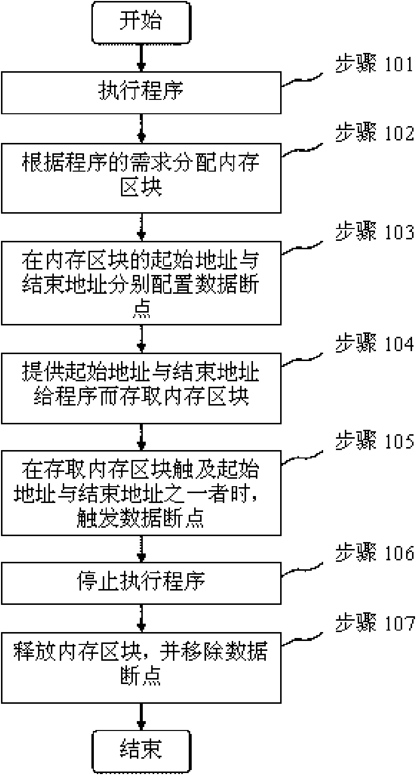
[0025] see figure 1 , figure 2 , the method includes the following steps:

[0026] Step 101: Execute the program.

[0027] Step 102: Allocate the memory block 10 according to the requirements of the program.

[0028] In this step, the size of the memory block 10 required by the program is first calculated, and then the memory block 10 is allocated according to the requirement, and the allocated memory block 10 can be increased according to the allocation ratio, wherein the allocation ratio is as the memory block 10 increases. Resource changes, in the debug version, only modify the allocation and release functions in memory management, or use the hook-in function (HOOK) to outsource a layer of memory management functions, according to the adequacy of system memory resources, increase the number of allocated resources when allocating The memory block 10, if the system memory resources are more abundant, the allocation ratio can be larger, and if the memory resources are tigh...


PUM


Abstract

The invention relates a method for monitoring a memory in real time by an embedded system, which comprises the following steps: (1) executing programs; (2) allocating a memory block according to the requirements of the programs; (3) respectively collocating data breakpoints at an initial address and an end address of the memory block; (4) providing the initial address and the end address to the programs and storing the memory block; and (5) triggering the data breakpoints when the stored memory block touches one of the initial address and the end address. The invention can position the mistake of program memory violation rapidly, lighten the debugging difficulty to the memory corruption problem for a user, accelerate the software development and removal speed, shorten the development cycle, save the developed labor cost and prompt the software quality.

Description

technical field [0001] The invention relates to a method for monitoring memory, in particular to a method for real-time monitoring of memory by an embedded system. Background technique [0002] In order to pursue high efficiency of program execution in embedded systems, the languages ​​used in software development often do not have memory garbage collection mechanisms, such as assembly, C, and C++. However, in the development of a huge software system, the phenomenon of memory corruption is unavoidable. In tens of thousands of lines of code, there will almost always be a link of memory corruption, making memory corruption a very difficult problem in the development process. Because the program needs to occupy memory when the program is executed, errors such as reading memory out of bounds will occur, especially in the system that introduces multi-thread (Multi-thread). The system is paralyzed, resulting in poor stability of the embedded system. [0003] In the field of per...

Claims


Application Information

Patent Timeline
IPC IPC(8): G06F11/36G06F9/50
Inventor 陈淮琰钟辉杨党林刘刚
Owner WUDI SCI & TECH (XIAN) CO LTD
Learn More