
Laser power supply device with constant power charge

A technology of laser power supply and power, which is applied in the direction of storage of electric energy, electrical components, etc., can solve the problems of low power factor, large voltage fluctuation range, insufficient charging capacity of the charging circuit, etc., and achieve the effect of constant charging power

Inactive Publication Date: 2010-01-13
UNITED WINNERS LASER CO LTD
View PDF0 Cites 4 Cited by
  • Summary
  • Abstract
  • Description
  • Claims
  • Application Information

AI Technical Summary

Problems solved by technology

[0003] The traditional laser charging power supply usually adopts the following two methods: one is that the grid voltage is directly charged to the energy storage element through bridge rectification. The advantages and disadvantages of this method are that the circuit is simple and the cost is low, but the charging voltage changes with the grid voltage And changes, thus affecting the stability of the laser output energy, and the charging voltage cannot be set arbitrarily; another way is to use transformer step-down switching power supply technology for capacitor rectification. The advantage of this method is that the voltage of the energy storage capacitor can be set arbitrarily , but the power factor is too low, because the charging circuit with fixed current or charging current proportional to the grid voltage is generally used, the output power of the power supply changes with the grid voltage, and the cost is high
[0004] Traditional power factor improved power supplies generally use constant current charging, but usually the voltage fluctuation range of the industrial power grid is very large. Due to the change of the power grid voltage, the charging capacity of the charging circuit will be insufficient or excessive, which will affect the laser output. power stability
At the same time, when there is a problem with the negative feedback discharge system, it is difficult for the control system to judge whether the negative feedback control is working normally

Method used


Image

  • Laser power supply device with constant power charge
  • Laser power supply device with constant power charge
  • Laser power supply device with constant power charge

Examples


Embodiment Construction

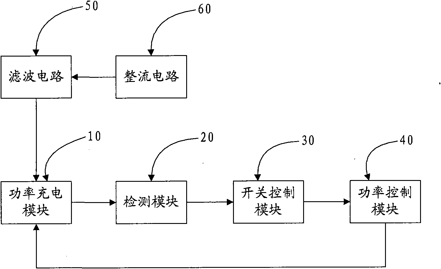
[0012] Such as figure 1 The system structure block diagram of the laser power supply device with constant power charging of the present invention is shown. The laser power supply device of the present invention is composed of a power charging module 10, a detection module 20, a switch control module 30 and a power control module. The power charging module 10 is connected with the rectification circuit 50 and the filter circuit 60. The rectification circuit 50 is mainly used to rectify the voltage of the external grid to obtain a unidirectional large pulsating DC voltage. The filter circuit 60 is used to rectify the unidirectional The large pulsating DC voltage is filtered to obtain a relatively smooth and small pulsating DC voltage, and the power charging module 10 uses the smooth and small pulsating DC voltage generated by the filter circuit 60 to charge the external energy storage element. External energy storage components include some capacitors, inductors and other energ...


PUM


Abstract

The invention relates to a laser power supply device capable of realizing constant power charge. The laser power supply device comprises a rectifying circuit, a filter circuit, a power charging module, a detection module, a switching control module and a power control module. The rectifying circuit rectifies a voltage of an external power grid to acquire a pulse direct-current voltage. The filter circuit filters the pulse direct-current voltage generated by the rectifying circuit to acquire a smooth direct-current voltage with small pulse. The power charging module charges an energy storage element by using the direct-current voltage generated by the filter circuit. The detection module detects the power charging module to generate a detection signal. The switching control module receives the detection signal generated by the detection module to generate a switching control signal. The power control module receives the switching control signal generated by the switching control module and generates a power control signal, and carries out debugging control for the charging power of the energy storage element by using the power control signal to keep the charging power of the energy storage element stable.

Description

technical field [0001] The invention relates to a laser power supply device, in particular to a laser power supply device capable of realizing constant power charging. Background technique [0002] Laser, namely Laser. With its unique monochromaticity, coherence and directionality and the resulting ultra-high brightness and ultra-short pulse, laser has brought a profound impact on science and technology. With the rise of the optoelectronic industry, laser science and Technology will gradually become the soul technology of the optoelectronic industry in the process of continuous maturity and development. At present, laser has been widely used in many fields such as communication, information detection, medical treatment, precision processing and military affairs. The laser power supply is an important part of the laser device, and its performance directly affects the technical indicators of the entire laser device. [0003] The traditional laser charging power supply usual...

Claims


Application Information

Patent Timeline
Patent Type & Authority Applications(China)
IPC IPC(8): H02J15/00
Inventor 牛增强
Owner UNITED WINNERS LASER CO LTD
Learn More