Battery with a heat conducting plate

A heat conduction plate and battery technology, which is applied to small-sized batteries/battery packs, secondary batteries, battery pack components, etc., can solve the problems of reducing the effective heat conduction cross-section of the heat conduction plate and reducing the possible efficiency

Inactive Publication Date: 2010-01-13
DAIMLER AG
View PDF1 Cites 10 Cited by
  • Summary
  • Abstract
  • Description
  • Claims
  • Application Information

AI Technical Summary

Problems solved by technology

However, the fracture window reduces the effective heat transfer cross-section of the heat transfer plate, thereby reducing its possible efficiency

Method used


Image

  • Battery with a heat conducting plate
  • Battery with a heat conducting plate
  • Battery with a heat conducting plate

Examples


Embodiment Construction

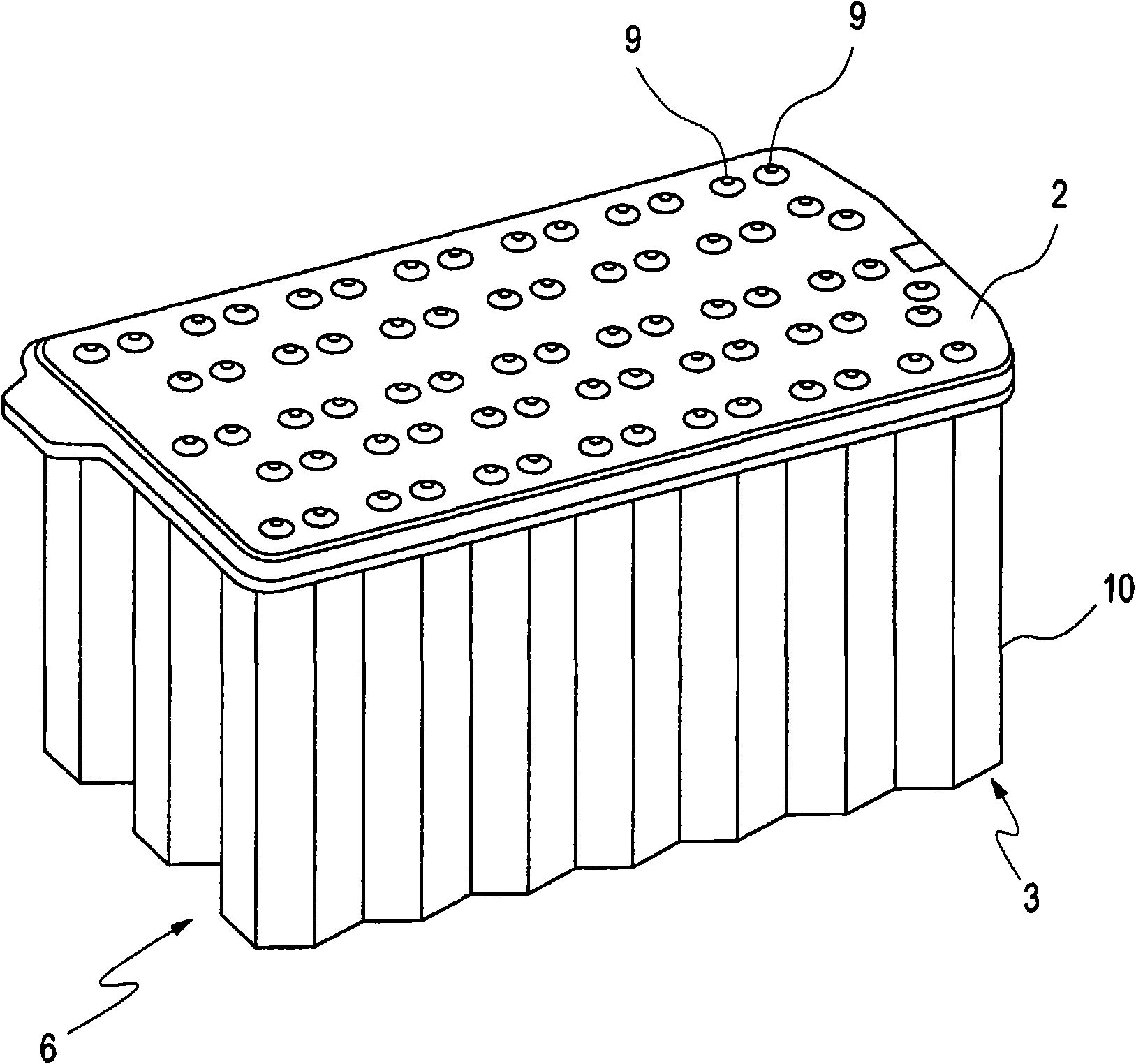
[0020] in figure 1 A conventional battery 1 is shown, which has a heat conducting plate 2 arranged on the bottom side. The battery 1 also has a plurality of cells 3 electrically connected to each other. The cell 3, which is preferably circular in cross-section, is arranged in a particularly completely enclosed battery housing 4. In the battery casing 4, the cell 3 is thermally placed on a thermally conductive plate 2 designed as a metal plate. The heat conducting plate 2 is provided with a cooling channel 5 for guiding the heat conducting medium. The cells 3 are arranged on the heat conducting plate 2 in such a way that their longitudinal axes are parallel to each other.

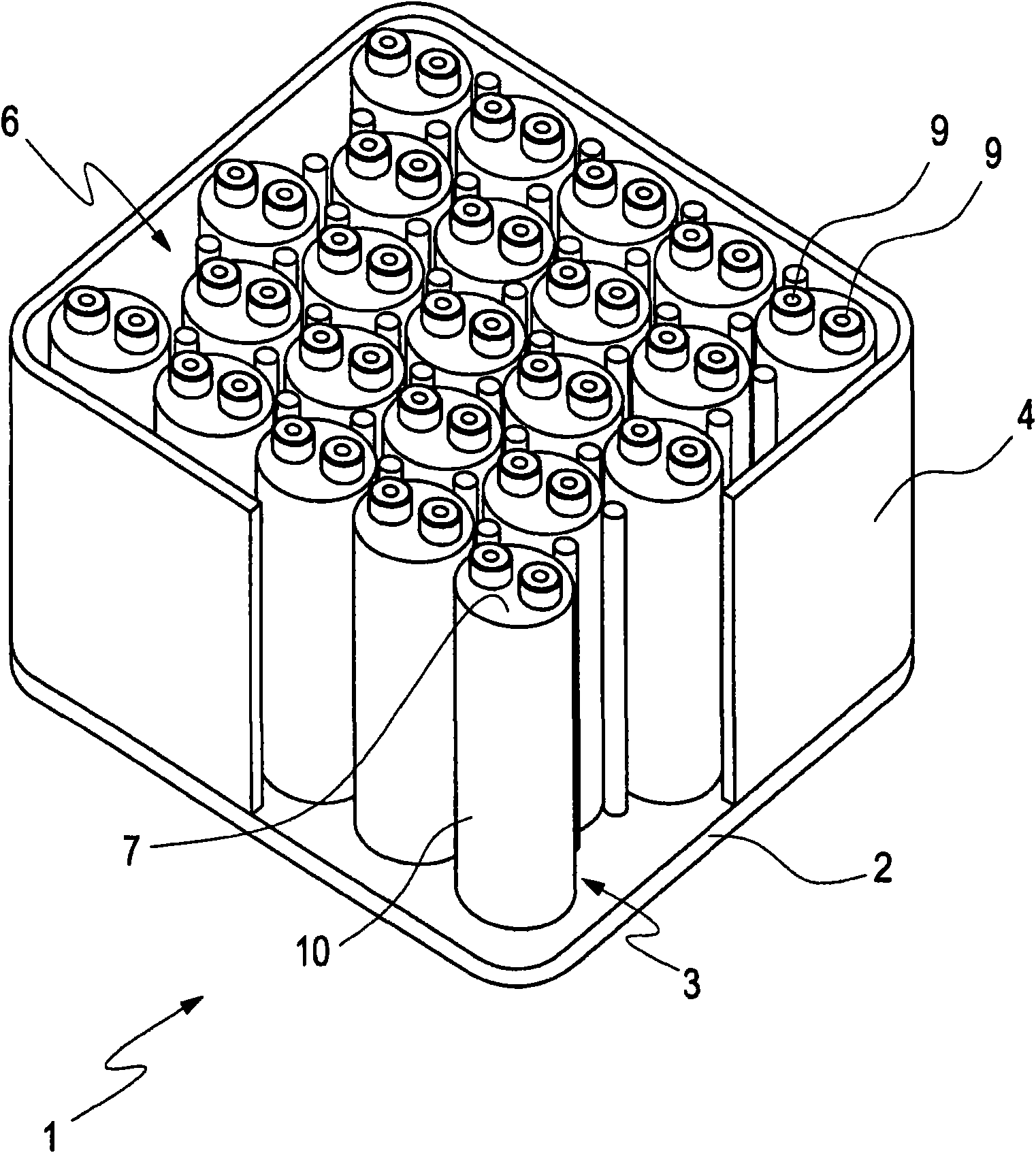
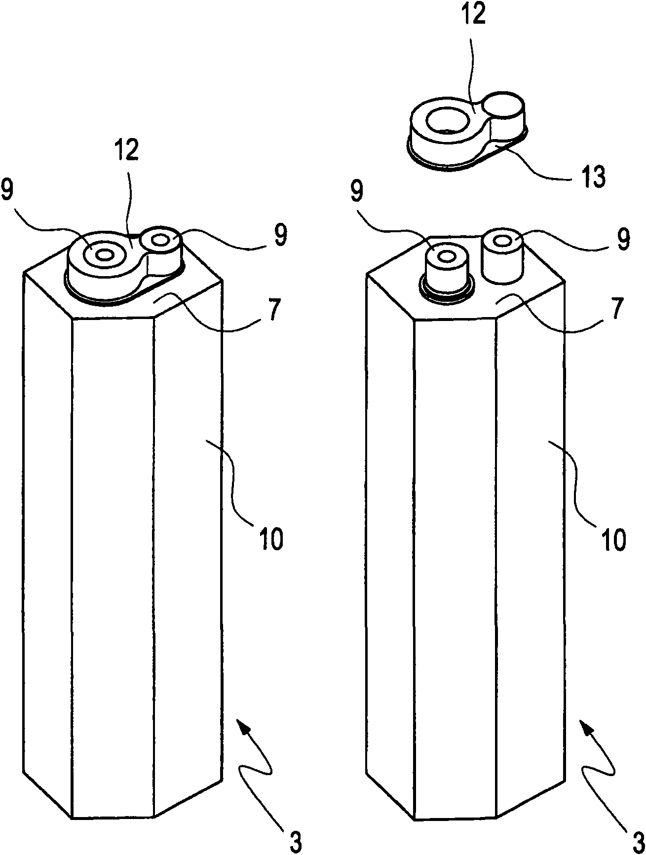
[0021] in figure 2 The middle is a perspective view showing a cell group 6 composed of a plurality of cells 3 of the battery according to the present invention, with a heat conducting plate 2 arranged on the top side and a cell 3 thermally connected to the heat conducting plate. Particularly due to the pack...


PUM


Abstract

The invention relates to a battery comprising a heat conducting plate for temperature control of the battery, wherein said battery comprises several parallel and / or serially connected single cells with a heat conducting connection to the heat conducting plate and a channel structure arranged in the heat conducting plate through which a heat conducting medium may flow and connection cross-sections for the channel structure extending from the heat conducting plate. In the region of the poles of the single cells the heat conducting plate has drillings through which the poles of the single cells extend. An insert piece made from an electrically insulating material is arranged about the pole of a single cell which at least partly contacts with the outer surface of the pole and which has at least one spacer extending radially from the pole, arranged in the region of the pole between the cover of the single cell and the heat conducting plate.

Description

Technical field [0001] The present invention relates to a battery / accumulator according to the preamble of claim 1 with a heat conducting plate for temperature control of the battery, such a battery is known, for example, from DE 19724020 A1 as the relevant basis . Background technique [0002] The battery known from the basic DE 19724020 A1 has a plurality of cells connected in parallel and / or in series, which cells are placed on a thermally conductive plate and are thermally connected to the thermally conductive plate. The evaporation part of the heat pipe is provided in the heat conducting plate. The heat-conducting pipe protrudes from the heat-conducting plate, especially from the battery casing, so that the condensing part of the heat-conducting pipe is outside the heat-conducting plate. With this design of the heat pipe, the temperature of the heat-conducting plate and the monomer can be controlled, especially for cooling during operation. Especially for lithium-ion batt...

Claims


Application Information

Patent Timeline
Patent Type & Authority Applications(China)
IPC IPC(8): H01M10/50H01M2/20H01M2/30H01M2/06H01M2/08H01M2/10H01M50/179H01M50/213H01M50/502H01M50/55H01M50/559
CPCH01M10/5004H01M2/305Y02E60/12H01M10/5057H01M2/1094H01M2/206H01M10/5016H01M10/503H01M2/06H01M2/08H01M10/504H01M2/1077H01M10/5053H01M10/625H01M10/653H01M10/6556H01M10/643H01M10/6554H01M10/613Y02E60/10H01M50/24H01M50/502H01M50/179H01M50/55H01M50/559H01M50/213
Inventor J·迈因特施尔D·施勒特尔P·舒尔茨
Owner DAIMLER AG
Why Eureka
Try Eureka