Clamping piece
A technology of clamping parts and clamping seats, which is applied in the field of clamping parts of file board folders, and can solve the problems of not being able to use both hands to organize papers, and inconvenient operations for putting or taking papers
- Summary
- Abstract
- Description
- Claims
- Application Information
AI Technical Summary
Problems solved by technology
Method used
Image

Examples
no. 1 example
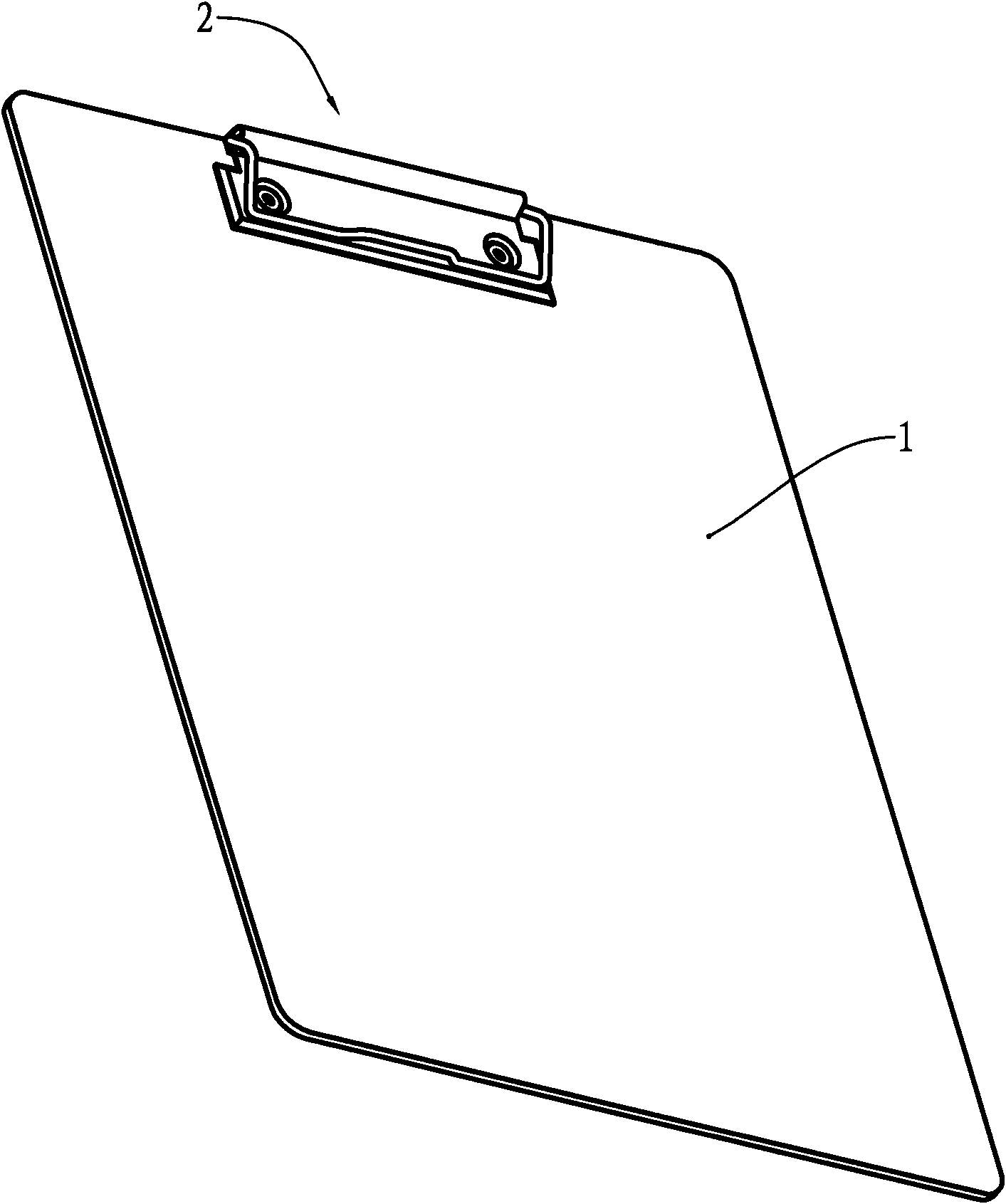
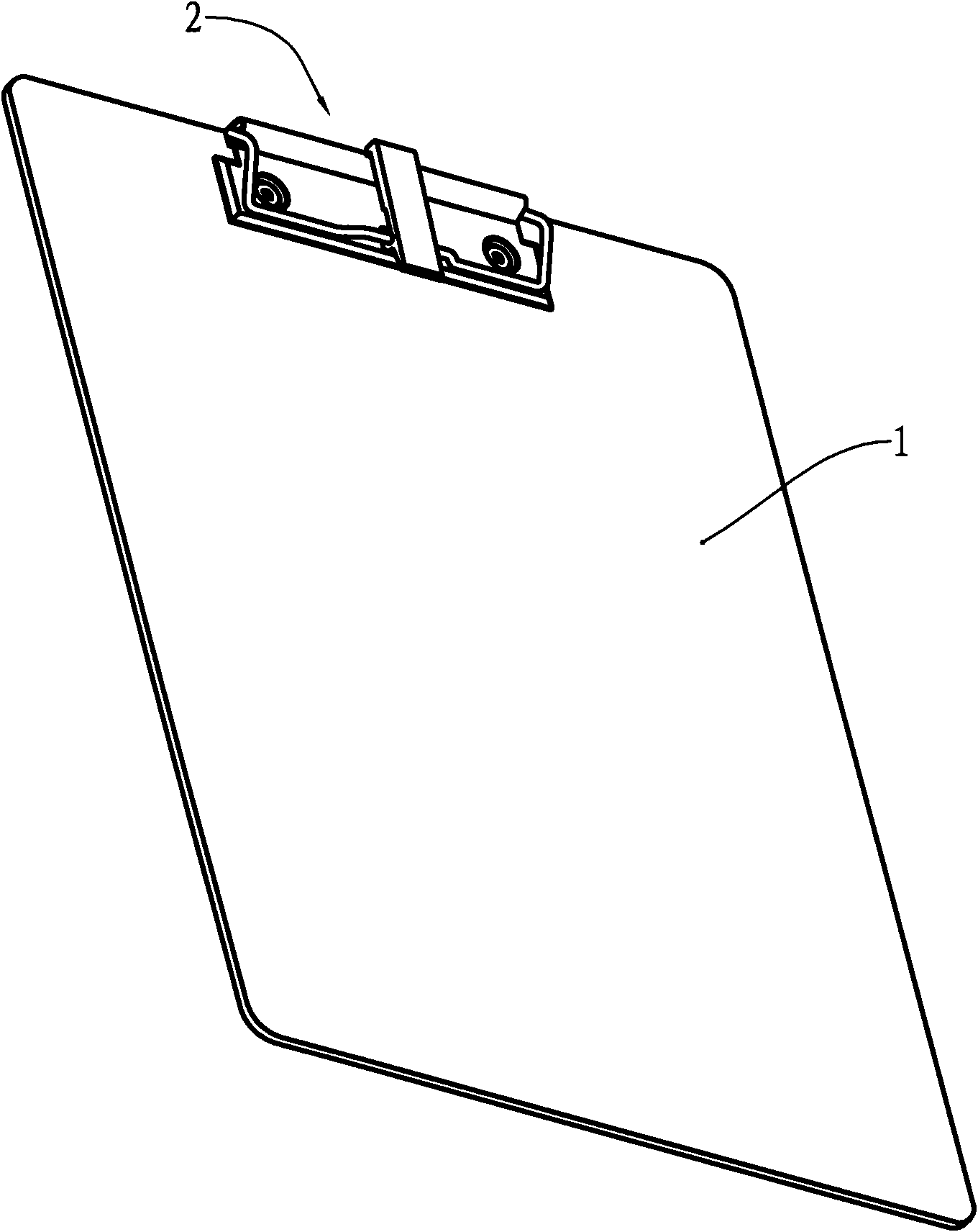
[0034] see image 3 , is a structural diagram of the file folder to which the first embodiment of the present invention is applied. Same as the existing file board holder, the file board holder has a base plate 1 and a clamping part 2 , and the clamping part 2 is fixed on one end of the base plate 1 .
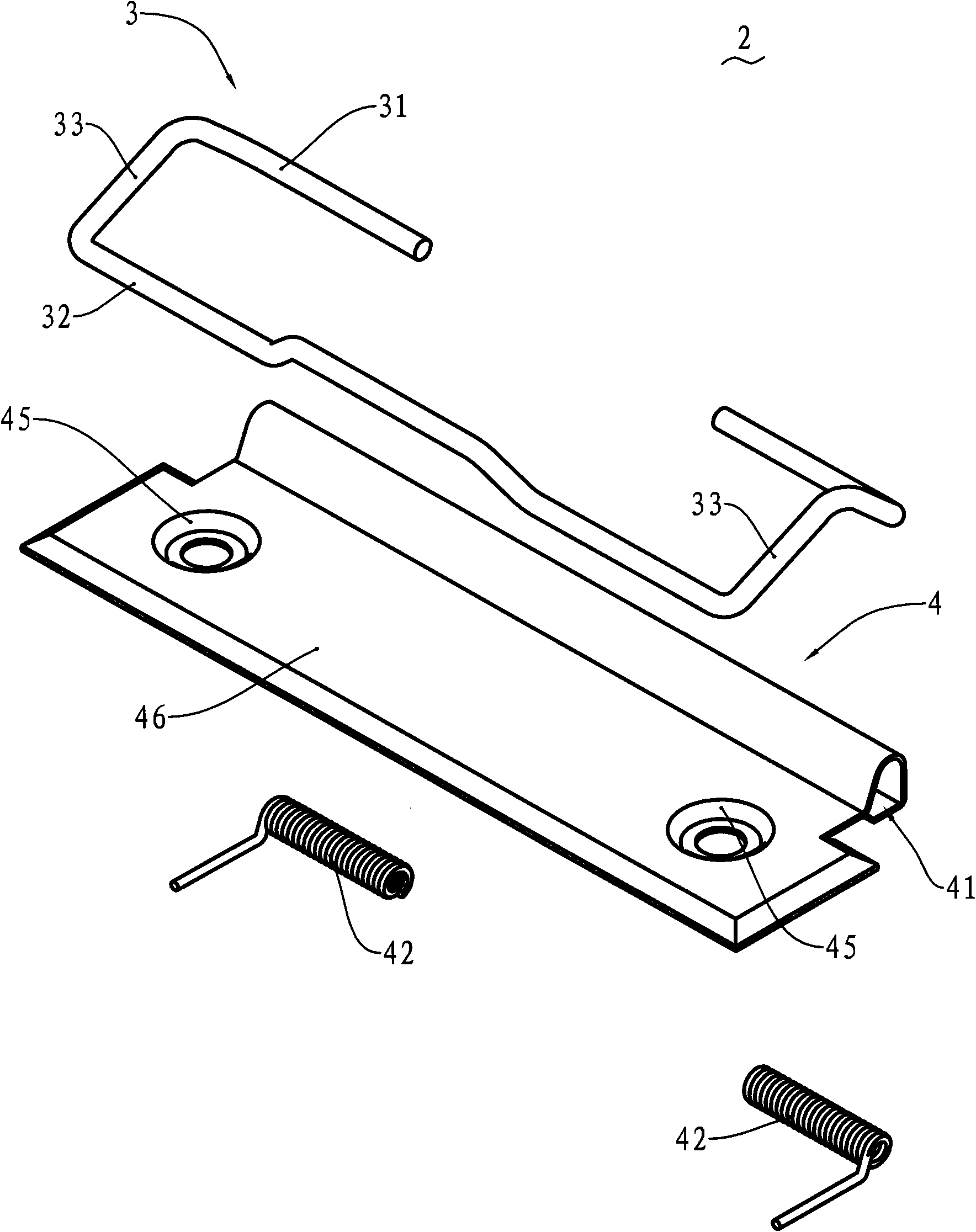
[0035] see Figure 4a , Figure 4b and Figure 5 , Figure 4a and Figure 4b It is a structural enlarged view of two different viewing angles of the first embodiment of the present invention, Figure 5 is an enlarged exploded view of the structure of the first embodiment. This embodiment includes a clamping base 4, the clamping base 4 is provided with a base plate 46, and one side of the base plate 46 is provided with a tubular hole 41, and two torsion springs 42 are installed in the tubular hole 41 close to both ends. The clamping part 2 also includes a pressure rod 3, the pressure rod 3 is composed of a hinged side 31, a bead side 32 opposite to the hinged side 31, and...
no. 2 example
[0048] see Figure 8 , is an enlarged view of the structure of the second embodiment of the present invention. Same as the first embodiment, the present embodiment also includes clamp seat 4, pressure rod 3 and connector 8, and the hole wall 44 of the tubular hole 41 of clamp seat 4 is also provided with a through hole as an engaging portion, and the pressure rod 3 is provided with axle 34 on the bead limit 32. Different from the first embodiment, the connecting piece 8 of this embodiment cancels the extension part, and its enlarged structure is as shown in Figure 9 shown.
[0049] Depend on Figure 9 It can be seen that one end of the connecting piece 8 is provided with a hook 81 as a connecting part, which is used to overlap or disengage with the through hole on the wall of the tubular hole 41 . The other end of the connecting piece 8 is provided with a bent portion 82 and forms a shaft hole 83 hinged with the shaft 34 .
[0050] When the user needs to put or pick up p...
no. 3 example
[0054] see Figure 11 and Figure 12 , are respectively the enlarged structure view and the exploded structure view of the third embodiment of the present invention. The clamping part 2 of this embodiment includes a clamping base 4 , the clamping base 4 is provided with a bottom plate 46 , one side of the bottom plate 46 is provided with a tubular hole 41 , and the hole wall 44 of the tubular hole 41 is also provided with a shaft seat 7 . The shaft seat 7 is composed of a seat body 71 and a shaft 72 mounted on the seat body 71 , where the two ends of the seat body 71 are provided with shaft holes 73 , and the shaft 72 is fixed in the shaft hole 73 .
[0055] In this embodiment, a pressing rod 3 is also provided. The pressing rod 3 includes a hinged edge 31 , a bead edge 32 and two side edges 33 . The hinged edge 31 is hinged in the tubular hole 41 through a torsion spring 42 . Moreover, an upwardly bent engaging portion 35 is provided at the middle of the bead edge 32 .
PUM
 Abstract
Description
Claims
Application Information
 - R&D
- Intellectual Property
- Life Sciences
- Materials
- Tech Scout
- Unparalleled Data Quality
- Higher Quality Content
- 60% Fewer Hallucinations
Browse by: Latest US Patents, China's latest patents, Technical Efficacy Thesaurus, Application Domain, Technology Topic, Popular Technical Reports.
© 2025 PatSnap. All rights reserved.Legal|Privacy policy|Modern Slavery Act Transparency Statement|Sitemap|About US| Contact US: help@patsnap.com