Laser dynamic balance adjustment method and device thereof

An adjustment method and an adjustment device technology, which are applied in static/dynamic balance testing, measuring devices, laser welding equipment, etc., can solve the problem that it is difficult to rotate the rotating body and the prism synchronously, and cannot process materials with high precision. Rotating body dynamic balance and other issues, to achieve the effect of small processing deformation, high production efficiency and high reliability

Active Publication Date: 2012-08-22
HANS LASER TECH IND GRP CO LTD
View PDF3 Cites 0 Cited by
  • Summary
  • Abstract
  • Description
  • Claims
  • Application Information

AI Technical Summary

Problems solved by technology

Since the adjustment part is contact processing, real-time adjustment cannot be achieved, and multiple adjustments are required, which is easily affected by human operation, low production efficiency, reliability and accuracy are not high; in addition, because the adjustment part is contact processing, and Contact processing will inevitably produce mechanical deformation on the material, and apply a certain stress to the material. The processing deformation is large, and only ordinary materials can be processed, but materials with high precision cannot be processed.
[0004] The more advanced idea of ​​laser adjustment dynamic balance was proposed as early as 1977. For details, see US Patent No. 4,037,076. This patent uses a prism that rotates synchronously with the rotating body to change the optical path to achieve dynamic dynamic balance adjustment. The body and the prism are not on the same axis, so it is difficult to realize the synchronous rotation of the rotating body and the prism (that is, the rotating body and the prism are relatively stationary); moreover, the prism can only scan the rotating body within a circular range, and cannot fully adjust the motion of the rotating body. balance

Method used


Image

  • Laser dynamic balance adjustment method and device thereof
  • Laser dynamic balance adjustment method and device thereof
  • Laser dynamic balance adjustment method and device thereof

Examples


Embodiment Construction

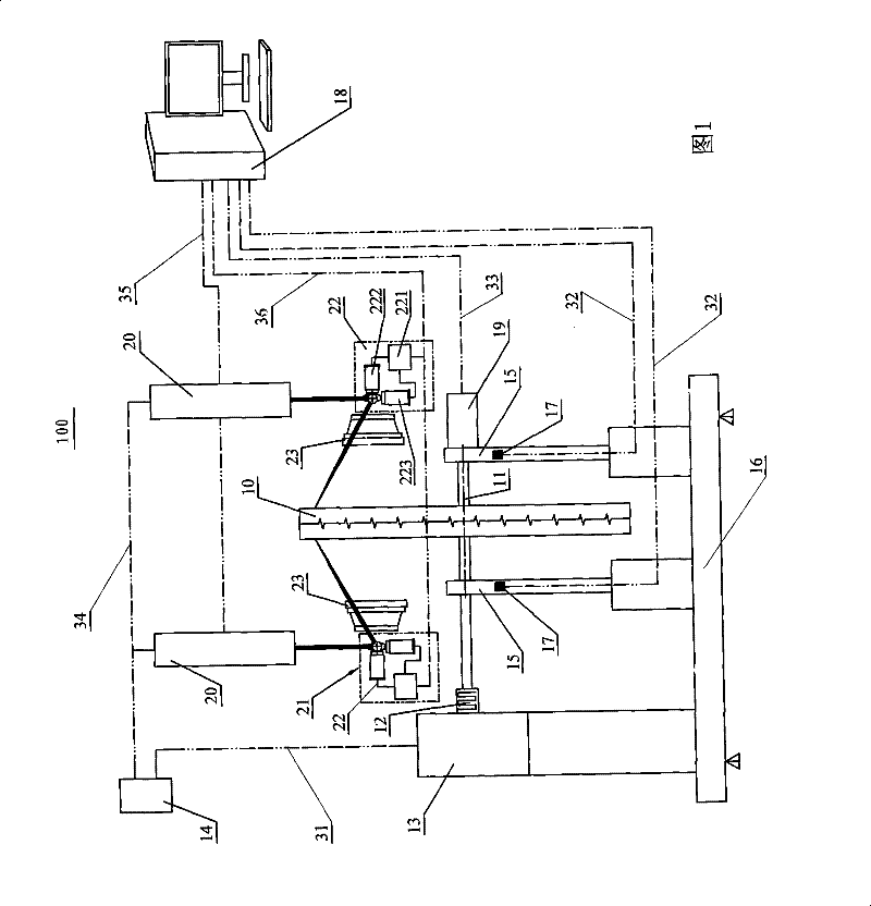
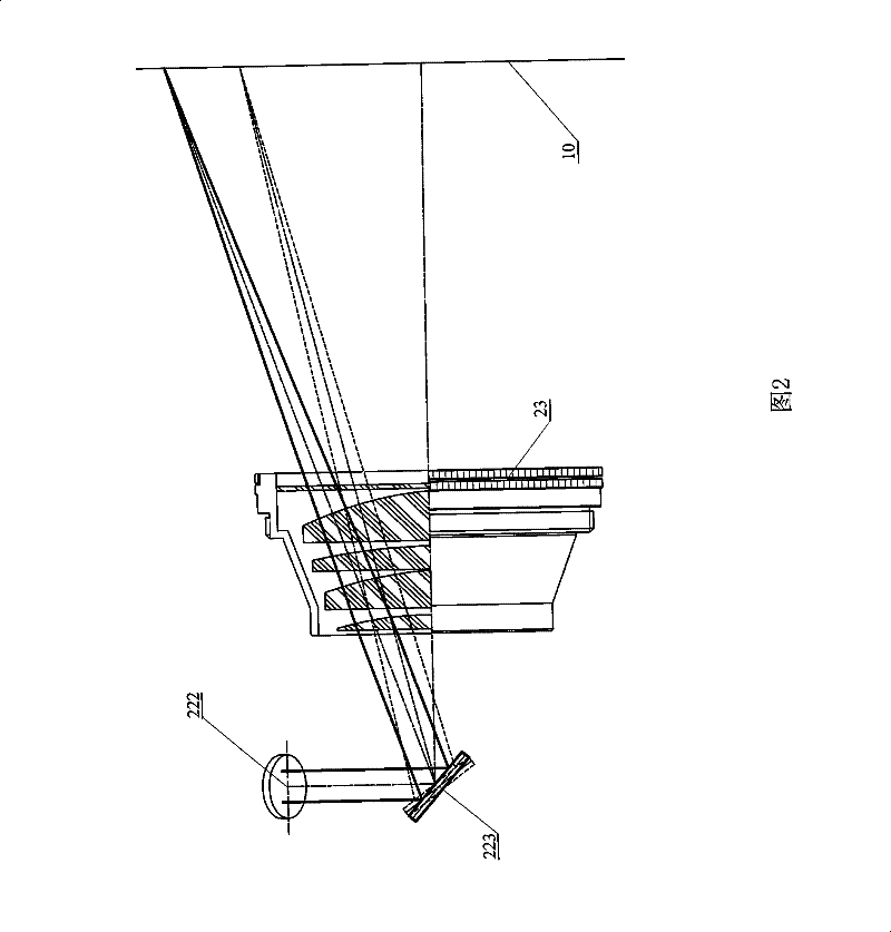
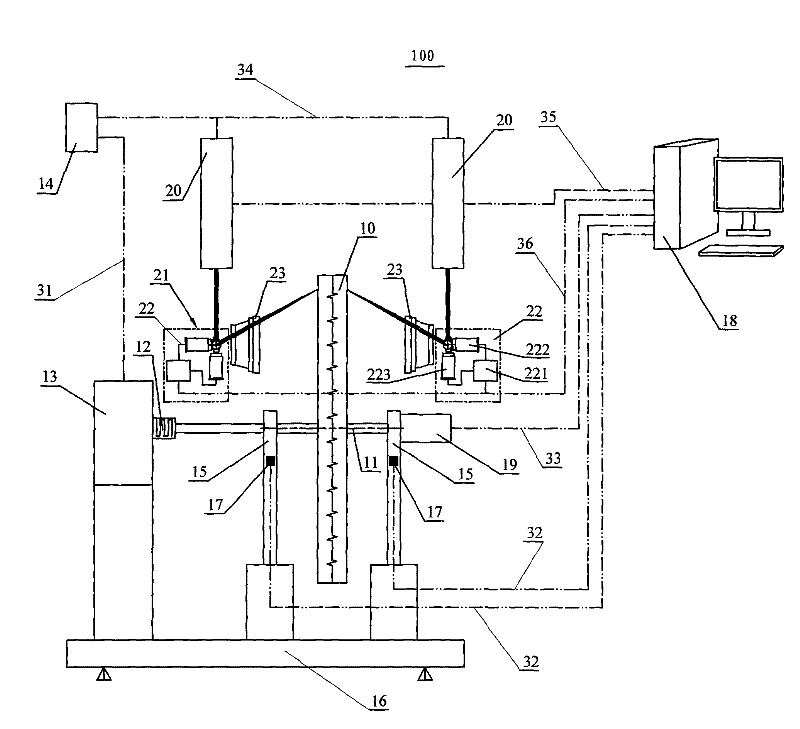
[0022] The present invention will be further described below in conjunction with the accompanying drawings and specific embodiments.

[0023] see figure 1 with figure 2 It is a structural schematic diagram of the first embodiment of the laser dynamic balance adjustment device of the present invention. The laser dynamic balance adjustment device 100 of the present invention is a kind of laser non-contact processing performance to adjust the dynamic balance of the workpiece 10. The workpiece 10 is a rotating body. Shaft workpieces, disc workpieces, crankshaft workpieces and other rotary workpieces, such as motor rotors, centrifugal fan blades, wind wheels, flywheels, pulleys, brake drums, horizontal CNC machine tools, CNC machine tools, eccentric wheels, etc., these The mass distribution of the workpiece 10 of the rotary part makes the centrifugal force system reach a balance when the rotary part works, so as to eliminate the additional dynamic pressure and reduce the harmful ...


PUM


Abstract

The invention provides a laser dynamic balance adjustment method and a device thereof. The dynamic balance of a revolving-body workpiece by use of laser; the unbalanced position of the workpiece is detected specifically through a vibration sensor and a position sensor; a laser beam is emitted by a laser system; and the unbalanced position is laser-cut through a vibrating mirror system and a flat-field mirror. The invention adjusts the dynamic balance of the workpiece through the non-contact machining property of laser; as the time delay of opening and closing laser is short, on-line adjustment on the revolving-body workpiece operating at high speed can be realized; due to the method of changing the light path of laser through the vibrating mirror system with large focal length and the flat-field mirror with high speed, tracked machining can be performed on the revolving-body workpiece in real time; and as the focus of a flat-field focusing mirror is a plane, laser in the plane has extremely high energy and is suitable for high-speed machining.

Description

【Technical field】 [0001] The invention relates to a laser dynamic balance adjusting device and a method thereof, in particular to adjusting the dynamic balance of a rotary workpiece by using the non-contact processing performance of laser. 【Background technique】 [0002] During mechanical movement, the mass distribution of each moving component is uneven due to manufacturing and assembly errors, uneven materials, etc., and the variable speed movement of the center of mass will generate inertial forces that vary in size and direction periodically. Due to the asymmetric structure of the rotary body, uneven material, manufacturing and installation errors, etc., it will cause eccentricity (the center of mass deviates from the centroid). Due to the eccentricity, the centrifugal inertial force will be generated when the rotary body is running, so that the rotary body is in an unbalanced state. , it is necessary to add or subtract counterweights on the rotary body to improve the ma...

Claims


Application Information

Patent Timeline
Patent Type & Authority Patents(China)
IPC IPC(8): G01M1/34B23K26/04B23K26/042
Inventor 高云峰任宁陈克胜张洪鑫
Owner HANS LASER TECH IND GRP CO LTD
Why Eureka
Try Eureka