Big viewing field scanning thermal imaging system based on staring imaging mode
An imaging system, staring imaging technology, applied in optics, measuring devices, instruments, etc., can solve problems such as the contradiction between field of view and spatial resolution
- Summary
- Abstract
- Description
- Claims
- Application Information
AI Technical Summary
Problems solved by technology
Method used
Image


Examples
specific Embodiment approach 1
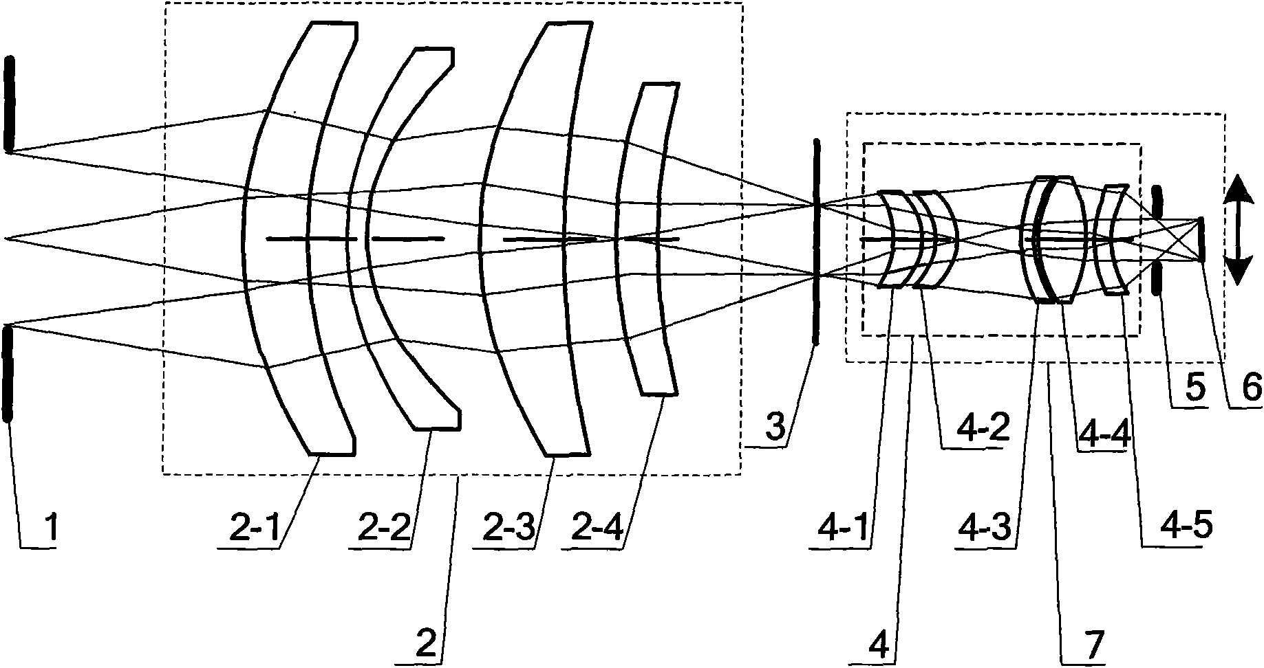
[0007] Specific implementation mode one: combine figure 1 , figure 2 and image 3 Describe this specific embodiment, the large field of view scanning thermal imaging system based on the staring imaging method described in this specific embodiment is composed of an aperture stop 1, a first lens group 2, a second lens group 4, a cold light stop 5 and a two-dimensional moving Composed of frame 7, the large field of view imaging system composed of aperture stop 1 and first lens group 2 adopts the image square telecentric optical path form, and the small field of view staring imaging system composed of second lens group 4 and cold light stop 5 is fixed on a two-dimensional On the mobile frame 7, the moving direction of the two-dimensional mobile frame 7 is perpendicular to the direction of the optical axis of the incident light, the input end of the small field of view staring imaging system is connected to the output end of the large field of view imaging system, and the cold li...
specific Embodiment approach 2
[0010] Specific implementation mode two: combination figure 1 Describe this specific embodiment. The difference between this specific embodiment and specific embodiment 1 is that the first lens group 2 is composed of a first lens 2-1, a second lens 2-2, a third lens according to the path of incident light. The lens 2-3 and the fourth lens 2-4 are formed sequentially. Other components and connections of this specific embodiment are the same as those of the first specific embodiment.
specific Embodiment approach 3
[0011] Specific implementation mode three: combination figure 1 Describe this specific embodiment. The difference between this specific embodiment and specific embodiment 1 or 2 is that the second lens group 4 is composed of a fifth lens 4-1, a sixth lens 4-2, The seventh lens 4-3, the eighth lens 4-4 and the ninth lens 4-5 are formed in sequence. Other components and connections of this specific embodiment are the same as those of specific embodiment 1 or 2.
PUM
 Abstract
Description
Claims
Application Information