Liquid crystal display and driving method

A technology of liquid crystal display and driving method, applied in static indicators, cathode ray tube indicators, instruments, etc., capable of solving problems such as different brightness

Active Publication Date: 2010-01-20
INNOLUX CORP
View PDF3 Cites 14 Cited by
  • Summary
  • Abstract
  • Description
  • Claims
  • Application Information

AI Technical Summary

Problems solved by technology

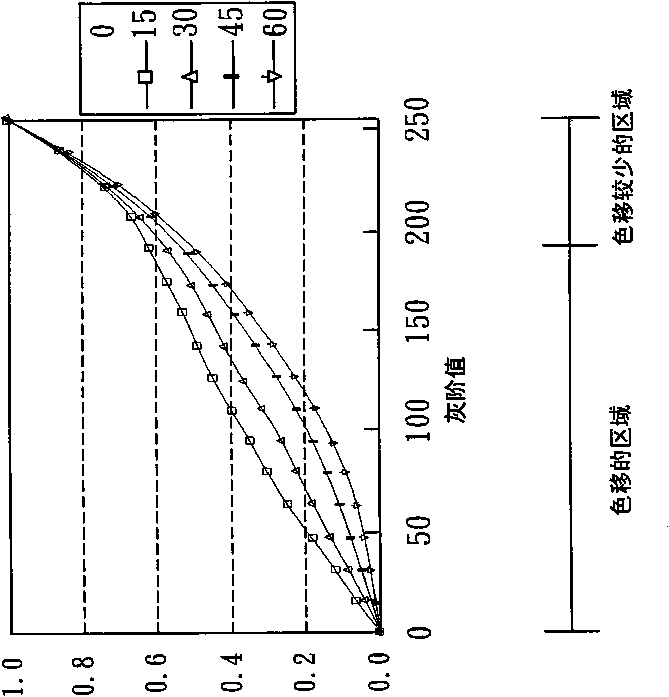
Therefore, different viewing angles will cause the displayed brightness to be different

Method used


Image

  • Liquid crystal display and driving method
  • Liquid crystal display and driving method
  • Liquid crystal display and driving method

Examples


Embodiment Construction

[0020] In order to describe the display method and display of the display of the present invention, the following detailed examples are used to illustrate them, but the scope of rights of the present invention is not limited to the following examples.

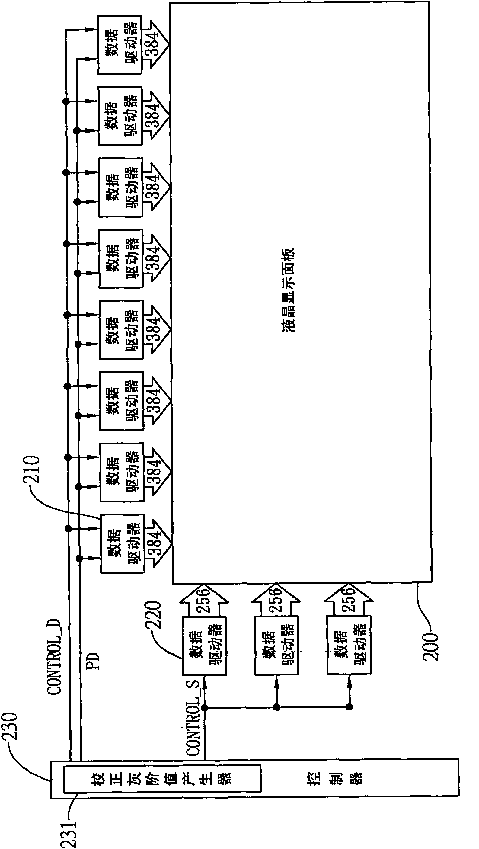
[0021] see Figure 2A , which is a system architecture diagram of the liquid crystal display in the first preferred embodiment of the present invention. Such as Figure 2A As shown, the liquid crystal display 200 with a resolution of 1024*768 is taken as an example for the following description. The liquid crystal display 200 is used to drive 1024 rows of red pixels, 1024 rows of green pixels and 1024 rows of blue pixels, with a total of 1024*3 data lines and 768 scan lines. The data lines and the scan lines are respectively driven by the data driver 210 and the scan driver 220 . Under the control of the data control signal Control_D output by the controller 230, the data drivers 210 and the scan drivers 220 sequentially rec...


PUM


Abstract

The invention provides a liquid crystal display and a driving method, in particular to application image segmentation technology which comprises the following steps: segmenting image data into a plurality of image blocks, carrying out image analysis on the image blocks, regulating low gray-scale image data of the image blocks into high gray-scale image data, outputting a backlight control signal to a backlight control module, controlling a corresponding backlight module block of the image block by the backlight control module, and darkening the backlight of the image block to reduce the problem of color migration of the image block.

Description

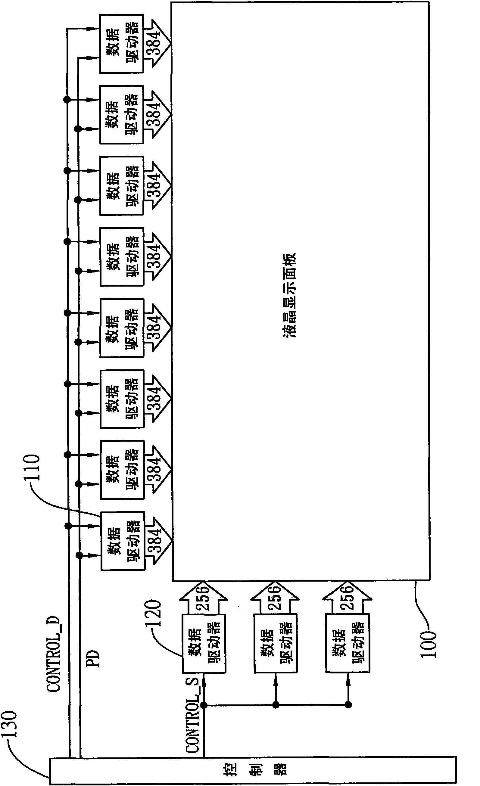
technical field [0001] The invention relates to a liquid crystal display and a driving method, in particular to an application of image segmentation technology to adjust image blocks belonging to high color shift areas to reduce color shift. Background technique [0002] see figure 1 , which is a system architecture diagram of a known liquid crystal display. Such as figure 1 As shown, the liquid crystal display 100 with a resolution of 1024*768 is taken as an example for the following description. The liquid crystal display 100 has 1024 rows of red pixels, 1024 rows of green pixels and 1024 rows of blue pixels for driving. There are 1024*3 data lines and 768 scan lines in total. The data lines and the scan lines are respectively driven by the data driver 110 and the scan driver 120 . Under the control of the data control signal Control_D output by the controller 130, the data drivers 110 and the scan drivers 120 sequentially receive multiple pieces of pixel data PD trans...

Claims


Application Information

Patent Timeline
IPC IPC(8): G09G3/36G09G5/02
Inventor 谢志勇何宜霖李嘉航杨富吉
Owner INNOLUX CORP
Why Eureka
Try Eureka