T-shaped linear ultrasonic motor oscillator

A linear ultrasonic motor and vibrator technology, applied in the direction of generators/motors, electrical components, piezoelectric effect/electrostrictive or magnetostrictive motors, etc., can solve the problem of low electromechanical coupling efficiency and mechanical output capacity of piezoelectric ultrasonic motors Poor, mechanical output capacity constraints and other issues, to achieve the effect of simple structure, increased amplitude and vibration speed, high electromechanical coupling efficiency

Inactive Publication Date: 2010-01-20
HARBIN INST OF TECH
View PDF0 Cites 24 Cited by
  • Summary
  • Abstract
  • Description
  • Claims
  • Application Information

AI Technical Summary

Problems solved by technology

[0004] In order to solve the problem that the mechanical output capability of the stator of the ultrasonic motor that is excited by pasting the piezoelectric ceramic sheet with the metal elastic body is restricted, the present invention provides a T-shaped linear ultrasonic motor vibrator
[0006] The piezoelectric ceramic element in the T-type linear ultrasonic motor vibrator of the present invention adopts a sandwich structure, and adopts d of piezoelectric ceramics with high electromechanical coupling efficiency 33 mode work, which solves the problem of low electromechanical coupling efficiency and poor mechanical output capability of pasted piezoelectric ceramic chip piezoelectric ultrasonic motor

Method used


Image

  • T-shaped linear ultrasonic motor oscillator
  • T-shaped linear ultrasonic motor oscillator
  • T-shaped linear ultrasonic motor oscillator

Examples


specific Embodiment approach 1

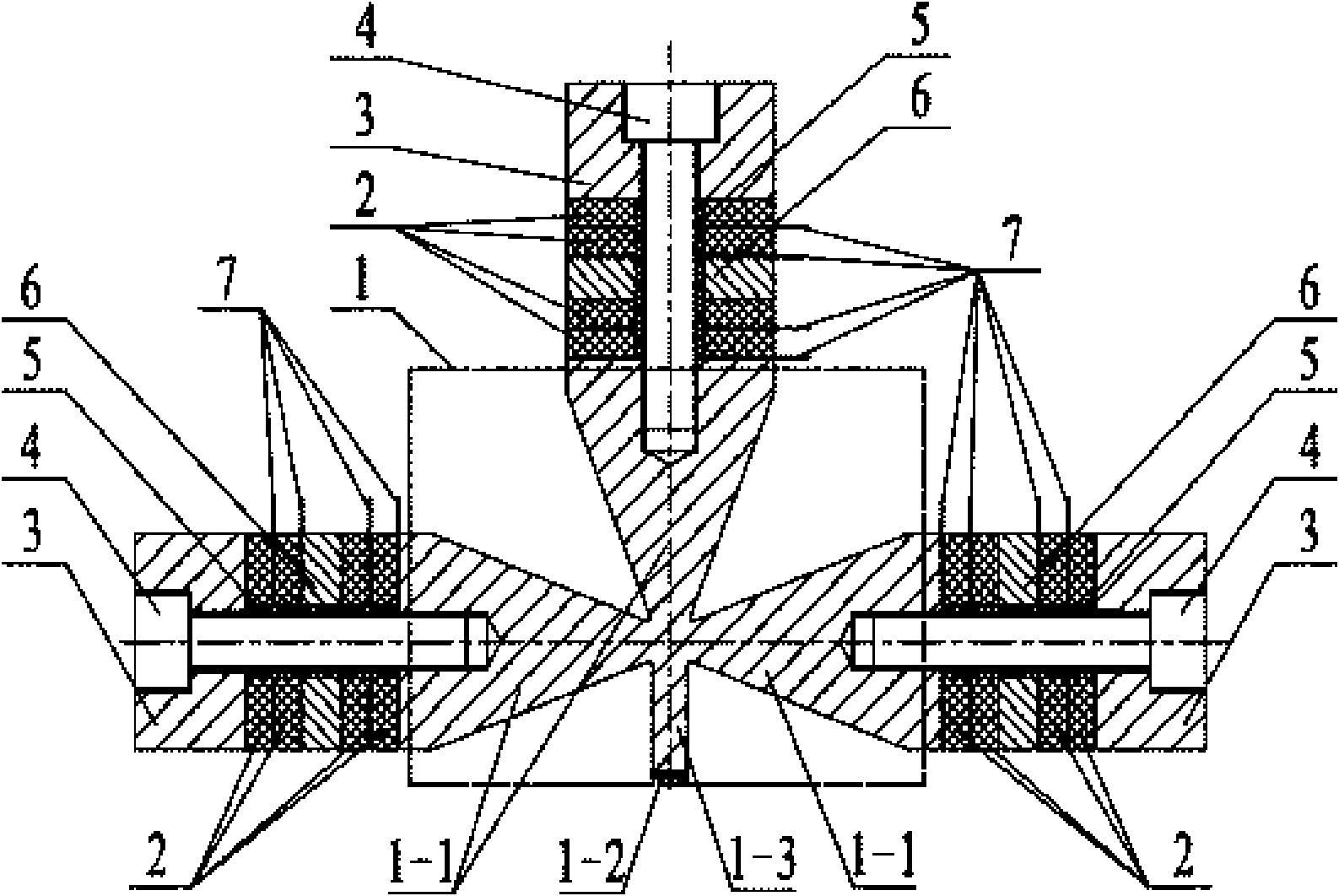
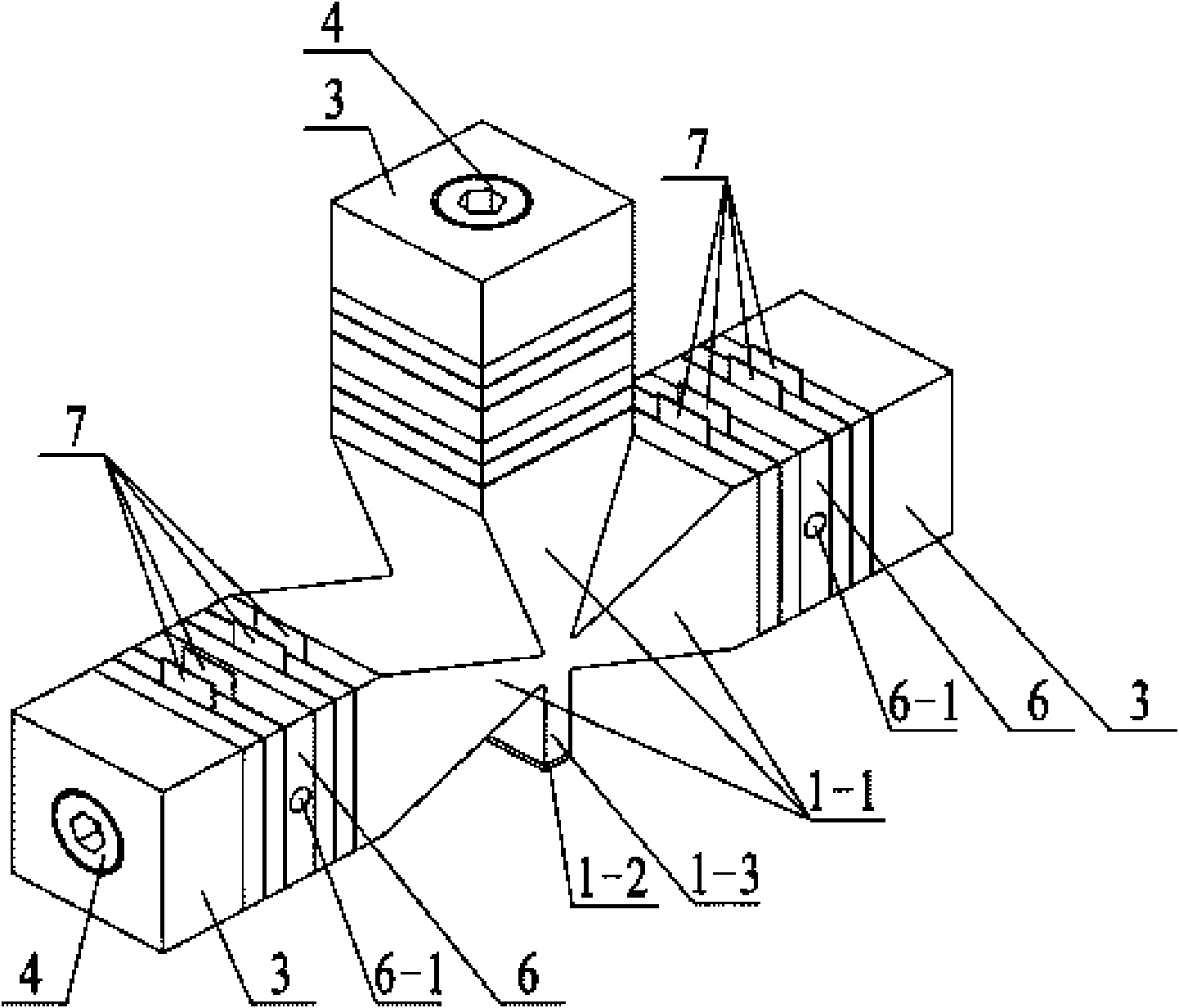
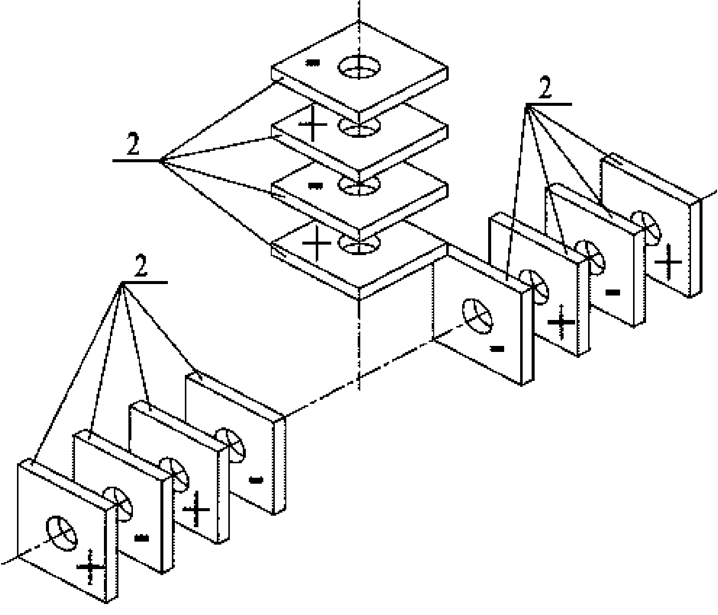
[0010] Specific implementation mode one: combine Figure 1 to Figure 4 Describe this embodiment, which includes a T-shaped front end cover 1, six pairs of piezoelectric ceramic sheets 2, three rear end covers 3, three fastening screws 4, three insulating sleeves 5, three flanges 6 and ten Two electrode sheets 7; it is characterized in that the T-shaped front end cover 1 includes three horns 1-1, a driving foot 1-3 and a wear-resistant liner 1-2; the horn 1-1 is a section It is a rectangular and gradually tapering quadrangular prism. The driving foot 1-3 is a cuboid. The small ends of the three horns 1-1 are integrally connected and arranged in a T shape. One end surface of the driving foot 1-3 is connected to three The position where the horns 1-1 are connected, and the center line of the driving foot 1-3 coincides with the center line of one of the horns 1-1, and the other two horns 1-1 are symmetrically arranged on the said The two sides of the center line are located on a ...

specific Embodiment approach 2

[0011] Specific implementation mode two: combination Figure 1 to Figure 3 This embodiment is described. The difference between this embodiment and the first embodiment is that the cross-sections of the piezoelectric ceramic sheet 2 and the rear end cover 3 are square or circular. Other compositions and connection methods are the same as those in Embodiment 1.

specific Embodiment approach 3

[0012] Specific implementation mode three: combination figure 2 This embodiment is described. The difference between this embodiment and the first or second embodiment is that a tapered positioning hole 6-1 is processed at the center of the side of the flange 6 . Other compositions and connection modes are the same as those in Embodiment 1 or 2. The tapered positioning hole 6-1 is used to support the vibrator and apply the pre-tightening force between the vibrator and the mover.


PUM


Abstract

The invention discloses a T-shaped linear ultrasonic motor oscillator, which relates to the technical field of a piezoelectric ultrasonic motor and aims at solving the problem that the mechanical output capacity of the prior ultrasonic motor stator is limited. T-shaped front end covers of the T-shaped linear ultrasonic motor oscillator are combined by small end surfaces of three amplitude rods and are arranged in a T shape, a drive foot is connected with a connection position of the amplitude rods, and the three amplitude rods and the drive foot form an integral member; piezoelectric ceramics are polarized along the thickness direction, and opposite to the polarization direction of every adjacent two pieces of piezoelectric ceramics on the same amplitude rod, the polarization ways of the piezoelectric ceramics of two amplitude rods on the same axial line are opposite, each fastening screw passes through a back end cover, the piezoelectric ceramics and a flange and is connected to a blind hole, and the piezoelectric ceramics and the flange are positioned between the back end cover and the amplitude rod, and a piece of electrode plate is arranged between the piezoelectric ceramics and the flange; and an insulating sleeve is fixed outside the fastening screw. The invention is applied to the manufacture field of the ultrasonic motor.

Description

technical field [0001] The invention relates to a T-shaped linear ultrasonic motor vibrator, which belongs to the technical field of piezoelectric ultrasonic motors. Background technique [0002] Piezoelectric ultrasonic motor is a kind of piezoelectric ultrasonic motor that uses the inverse piezoelectric effect of piezoelectric ceramics to excite vibration in the ultrasonic frequency range in the elastic body, and forms a particle motion with a specific trajectory at a specific point or area on the surface of the elastic body, and then passes through the stator, The frictional coupling between the rotors converts the microscopic motion of the particle into the macroscopic motion of the rotor. It has the advantages of low speed and high torque, no need for a transmission mechanism, no electromagnetic interference, fast response, and self-locking when power is off. As a piezoelectric driver, it has Very wide range of applications. [0003] Due to the simplicity of the excita...

Claims


Application Information

Patent Timeline
Patent Type & Authority Applications(China)
IPC IPC(8): H02N2/04
Inventor 陈维山刘英想石胜君刘军考
Owner HARBIN INST OF TECH
Why Eureka
Try Eureka