Method for separating brightness and chrominance in composite analog television signal

An analog TV, composite technology, applied in the direction of luminance and chrominance signal processing circuits, etc., can solve problems such as inability to separate composite signals

Inactive Publication Date: 2010-01-20
HIMAX MEDIA SOLUTIONS
View PDF0 Cites 2 Cited by
  • Summary
  • Abstract
  • Description
  • Claims
  • Application Information

AI Technical Summary

Problems solved by technology

Therefore, it is not possible to effectively separate the complex signals if only the

Method used


Image

  • Method for separating brightness and chrominance in composite analog television signal
  • Method for separating brightness and chrominance in composite analog television signal
  • Method for separating brightness and chrominance in composite analog television signal

Examples


Embodiment Construction

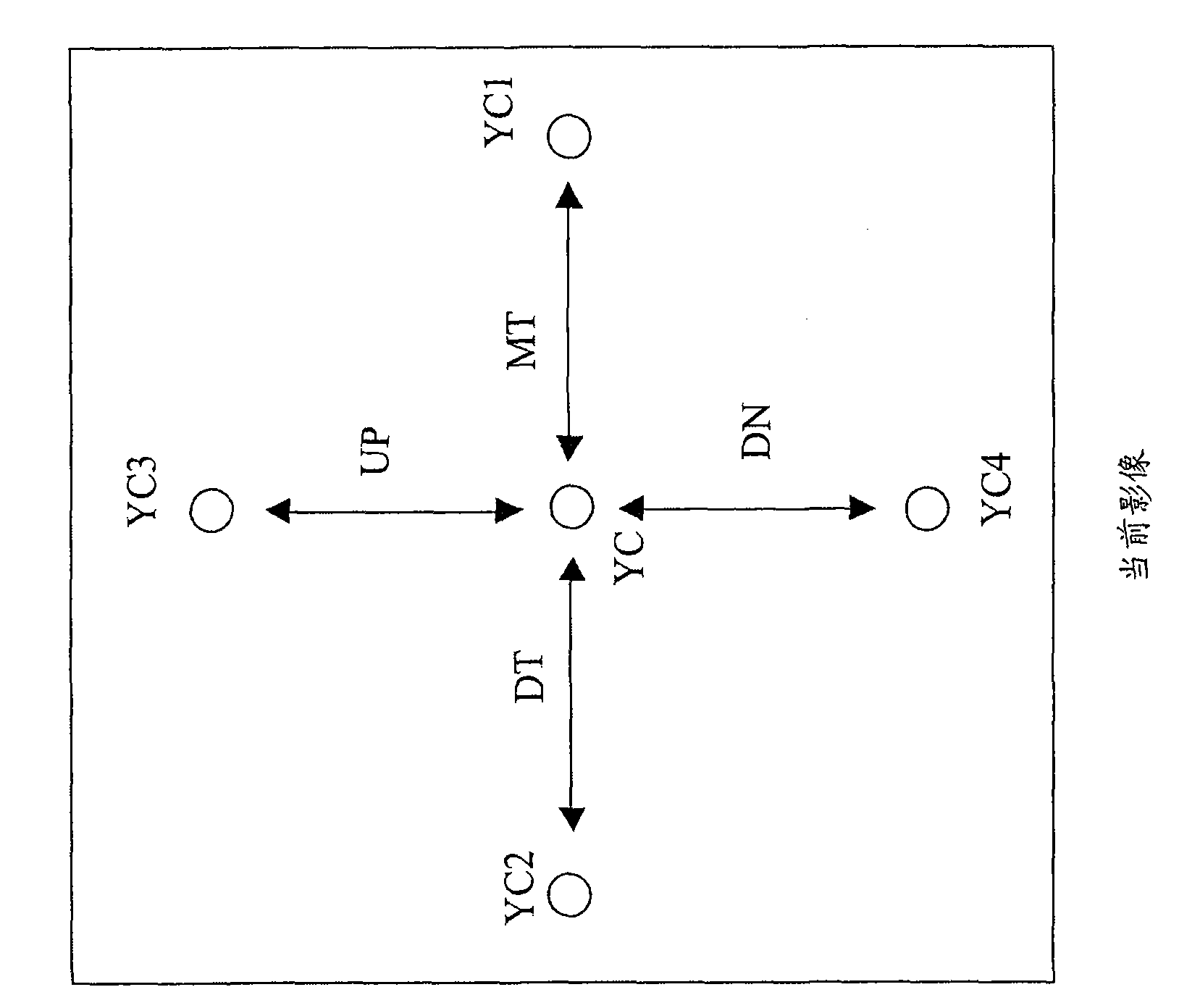
[0019] For a composite analog TV signal, it includes a luminance (Y) signal and a chrominance (C) signal, and has several continuous images encoded therein. Figure 1A It is a schematic diagram illustrating a processed pixel and its adjacent pixels in a current image according to an embodiment of the present invention. Such as Figure 1A As shown, the current image includes a processing pixel (such as: YC) and its horizontally adjacent and vertically adjacent pixels (such as: YC1, YC2, YC3 and YC4), wherein the processing pixel YC and its horizontally adjacent pixels YC1 and YC2 There are difference values ​​(such as: gray scale difference) MT and DT between them, and there are difference values ​​(such as: gray scale difference) UP and DN between the processing pixel YC and its vertically adjacent pixels YC3 and YC4 respectively.

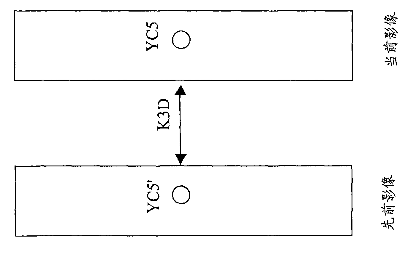
[0020] Figure 1B is a schematic diagram illustrating a continuous image with the current image and its previous image according to an embodiment ...


PUM


Abstract

The invention discloses a method for separating brightness and chrominance in a composite analog television signal, which comprises the following steps: measuring a first difference between horizontal adjacent pixels, a second difference between vertical adjacent pixels and a third difference between time sequence adjacent pixels coded in the composite analog television signal; inter-comparing the first difference, the second difference and the third difference to acquire a minimum difference as a coefficient of a weighting function; and filtering the composite analog television signal synchronously by a two-dimensional comb filter and a third-dimensional comb filter according to the weighting function based on the minimum difference to acquire a brightness signal and a chrominance signal, wherein partial magnitude of the composite analog television signal filtered by the two-dimensional comb filter and the third-dimensional comb filter is determined by the weighting function.

Description

technical field [0001] The invention relates to a method for separating luminance and chroma, in particular to a method for separating luminance and chroma in composite analog television signals. Background technique [0002] In a common color TV, the analog TV signal is usually transmitted in the form of a composite signal including luminance (Y) and chrominance (C). Therefore, the process of separating the composite signal into luminance signal and chrominance signal is very important, and this process is usually implemented by a comb filter. [0003] In addition, in order to obtain a better filtering effect when implementing the above separation steps, the static image signal is usually filtered by a three-dimensional (3D) comb filter, while the image signal with dynamic changes is obtained by Two-dimensional (2D) comb filter for filtering processing. [0004] However, the above-mentioned composite signal often includes still image signals and image signals with dynamic...

Claims


Application Information

Patent Timeline
IPC IPC(8): H04N9/78
Inventor 陈星嘉黄铃琇
Owner HIMAX MEDIA SOLUTIONS
Why Eureka
Try Eureka