
Groove joint type buckling restrained brace device

A technique for buckling bundle bracing and supporting parts, which is applied in the field of buckling bundle bracing devices, which can solve the problems of easy occurrence of buckling, high difficulty, and increased fixing difficulty.

Active Publication Date: 2010-01-27
蔡克铨 +1
View PDF0 Cites 6 Cited by
  • Summary
  • Abstract
  • Description
  • Claims
  • Application Information

AI Technical Summary

Problems solved by technology

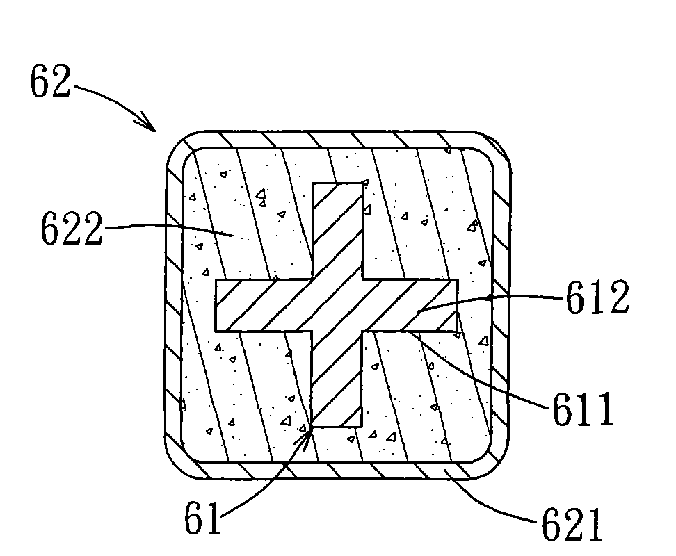
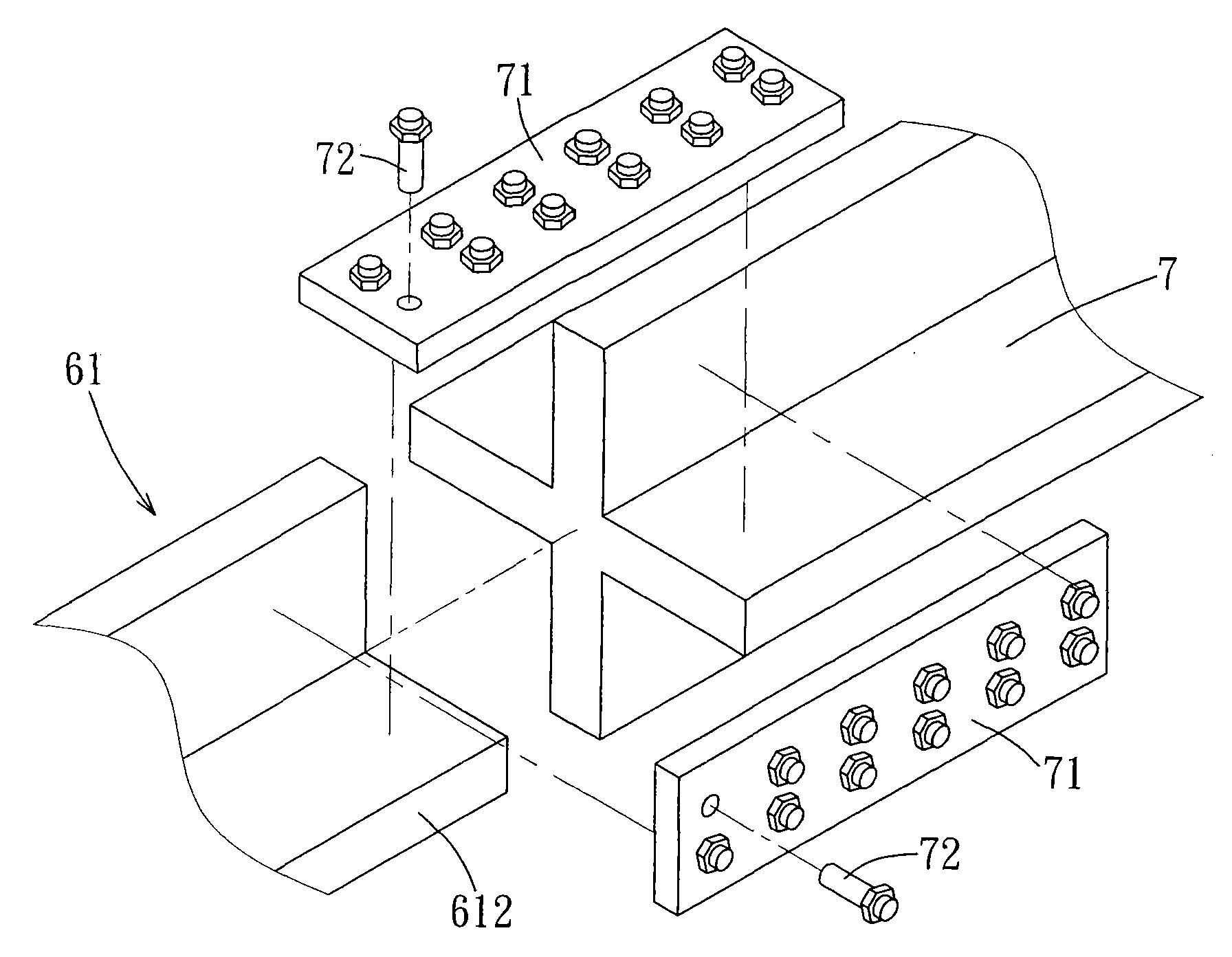
[0008] There are two defects in the "single-pipe double-core" buckling support device 8: first, the distance d must correspond to the thickness t of the joint plate 7'. When d is less than t, it cannot be plugged. When d is much greater than t, Then the difficulty of fixing increases, especially the thickness of the joint plate 7' has various specifications, which must be investigated separately before installation, and the pre-work is quite time-consuming; second, because the two elongated steel plates 811 are arranged in parallel, if external disturbances occur The principal stress is perpendicular to the 811 plate surface of the steel plate, buckling is very easy to occur
However, when assembling, since the first combination 91 and a second combination 92 are separated from each other, they must be erected at the opposite positions on both sides of the joint plate 7 "before they can be bolted with the bolt unit 72". In addition, Then weld and fix the first combination 91 and a second combination 92, the difficulty of the whole assembly process is relatively high

Method used


Image

  • Groove joint type buckling restrained brace device
  • Groove joint type buckling restrained brace device
  • Groove joint type buckling restrained brace device

Examples


Embodiment Construction

[0057] Below in conjunction with accompanying drawing and embodiment the present invention is described in detail:

[0058] refer to Figure 10 , Figure 11 and Figure 12 In the first preferred embodiment of the present invention, the groove-joint buckle restraint system support device 100 is fixed between two joint plates 210 of a building steel frame 200, and includes a first axial force member 1 and a restraint unit 2 .

[0059] The first axial force member 1 includes a central section 11 and two connecting sections 12 extending integrally from both ends of the central section 11. The central section 11 has a long plate-shaped main body 111, and each connecting section 12 has a The long plate-shaped main body 111 has a parallel first support portion 121 and a first contact portion 122 protruding from the first support portion 121 . In this embodiment, the first supporting part 121 defines a first groove 123 for inserting the connecting plate 210 in the axial direction ...


PUM


Abstract

The invention discloses a groove joint type buckling restrained brace device, which is fixed between two joint plates of a building steel framework and comprises a first shaft force component and a confining unit cladding the first shaft force component. The first shaft force component comprises a central section provided with a long slab shaped body, and two assembling sections extending integrally from two ends of the central section respectively, wherein each one of the assembling sections is provided with a first supporting part parallel with the long slab shaped body and a first contact part protruding from the first supporting part; the first supporting part is provided with a first groove for correspondingly inserting one of the joint plates along the axial direction from the outer end face; and the first contact part is used for contacting the joint plate inserted in the first groove in parallel. The confining unit comprises an encircling part cladding the periphery of the first shaft force component at intervals, and a restraining component which is positioned between the first shaft force component and the encircling part and generates a radial restraining force to the first shaft force component.

Description

technical field [0001] The present invention relates to a buckle-bundle support device, in particular to a groove-connected buckle-bunch support device. Background technique [0002] Buckling Restrained Braces (BRB) is an energy dissipation device installed between the steel frames of a building. When external disturbances (especially seismic force disturbances) occur, the energy dissipation device first bears the energy. It even replaces the steel frame to cause damage first, so as to avoid damage to the steel frame of the building. Basically, the buckling support device includes an axial force member and a confinement unit. The force member provides radial restraining force, increasing its ability to resist buckling. According to the different designs of the axial force member and the containment unit, it can be roughly divided into three types: "single-tube single-core", "single-tube dual-core" and "double-tube dual-core". Type and lap type and other construction metho...

Claims


Application Information

Patent Timeline
IPC IPC(8): E04B1/98E04B1/36E04B1/18
Inventor 蔡克铨魏志毓
Owner 蔡克铨
Learn More