Movable optical fiber connector with improved structure

An optical fiber connector and activity technology, applied in the field of optical connection devices, can solve the problems of unreliable fixation and difficult fixation of optical cables, and achieve the effects of speeding up docking, easy maintenance and replacement, and reliable fixation

Inactive Publication Date: 2010-01-27
沈群华
View PDF1 Cites 2 Cited by
  • Summary
  • Abstract
  • Description
  • Claims
  • Application Information

AI Technical Summary

Problems solved by technology

[0002] With the development of high-speed broadband communication technology, the application of optical fiber transmission is becoming more and more extensive. Therefore, the demand for optical fiber and optical cable continues to rise. , it is necessary to test the optical performance of each optical fiber in the optical cable; the connection required in the test is a fast active connection. Chinese patent ZL200720146424.4 discloses an active optical fiber connector, which is very suitable for factory testing and other active connections. However, unfortunately, the V-shaped grooves on both sides of this fiber optic connector and the corresponding pressing blocks are placed horizontally, and the optical cable to be tested is often not easy to fix. When the optical cable slips slightly, the tested The optical fiber will slide away from the V-shaped grooves on both sides, and the purpose of reliable fixation cannot be achieved

Method used


Image

  • Movable optical fiber connector with improved structure
  • Movable optical fiber connector with improved structure
  • Movable optical fiber connector with improved structure

Examples


Embodiment Construction

[0020]

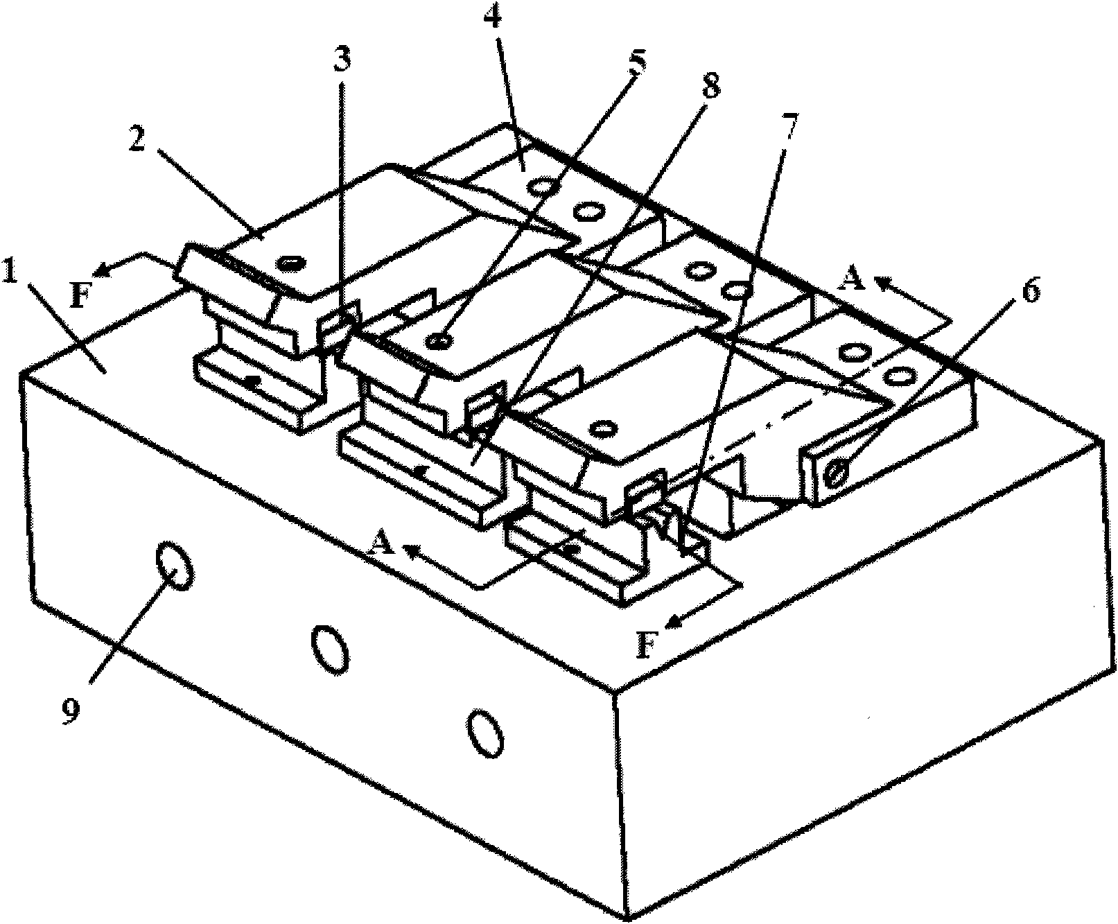
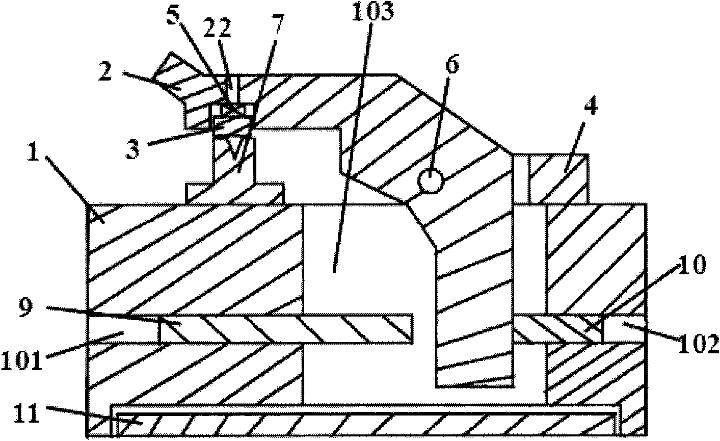
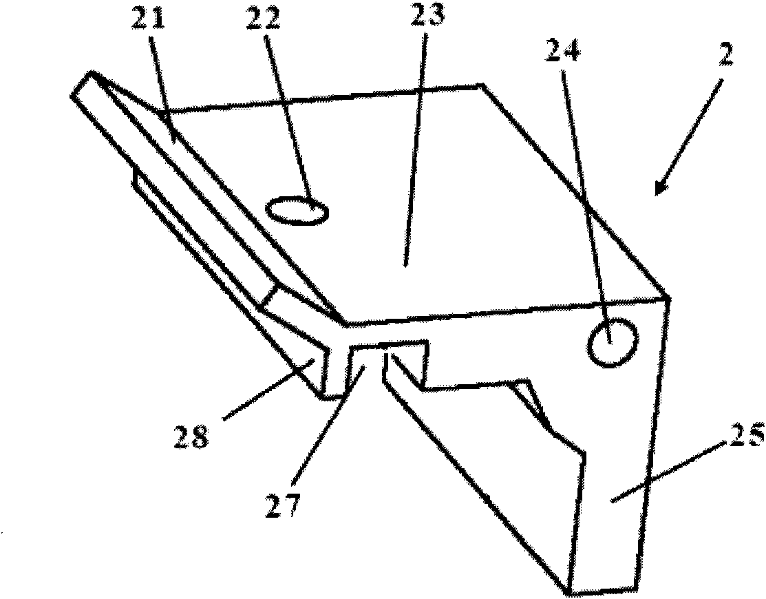
[0021] Such as figure 1 and figure 2 As shown, the optical fiber connector with improved structure disclosed by the present invention includes: a base 1, the upper bottom surface of the base 1 near the front end is fixed with a V-shaped groove 7 on the left and a right and a V-shaped groove 8 in the middle, and the three V-shaped grooves 8 The groove is used to accommodate the reference optical fiber and the optical fiber to be tested; three concave plates 4 are fixed on the bottom surface of the base 1 near the rear end surface, the concave surface of the concave plate 4 faces the front end of the base 1, and the rear end of the pressure plate 2 is inserted In the recess of the board 4, three shafts 6 passing through the right side of the concave board 4 connect the three concave boards 4 with the three pressure plates 2 respectively. 2. The fiber tightness adjustment spring 5 located in the groove of the pressure plate 2 and the pressure block 3 located below t...


PUM


Abstract

The invention discloses a movable optical fiber connector with an improved structure, belonging to the technical field of connectors. The movable optical fiber connector comprises a base, wherein a left V-shaped groove, a middle V-shaped groove and a right V-shaped groove are sequentially fixed on the base and used for accommodating reference measured optical fibers; three concave-shaped plates connected with a pressing plate through an axle are also fixed on the base, and a thread hole on the pressing plate, a puddlability adjusting spring in a groove of the pressing plate and a block below the spring are connected together through screws; the groove of the pressing plate is positioned above the V-shaped grooves; the optical fibers are tightly pressed by the lower end surface of the pressing block, a front positioning pin and a back positioning pin screwed on the thread holes on the front and back end surfaces of the base are used for regulating the travel of the pressing plate, and the front positioning pin and the back positioning pin are positioned at the front side and the back side of the pressing plate. The movable optical fiber connector is characterized in that extending parts of the base lines of the left V-shaped groove and right V-shaped groove and the base line of the middle V-shaped groove are crossed with each other to form an included angle beta; and the base lines of the left V-shaped groove and right V-shaped groove and the base line of the middle V-shaped groove are in the same plane, therefore, the optical fiber connector has the characteristics of satisfying rapid connection, having long service life and easy maintenance, and more reliably fixing the measured optical fiber.

Description

technical field [0001] The invention relates to an optical connection device, in particular to an active optical fiber connector with improved structure. Background technique [0002] With the development of high-speed broadband communication technology, the application of optical fiber transmission is becoming more and more extensive. Therefore, the demand for optical fibers and optical cables continues to rise. , it is necessary to test the optical performance of each optical fiber in the optical cable; the connection required in the test is a fast active connection. Chinese patent ZL200720146424.4 discloses an active optical fiber connector, which is very suitable for factory testing and other active connections. However, unfortunately, the V-shaped grooves on both sides of this fiber optic connector and the corresponding pressing blocks are placed horizontally, and the optical cable to be tested is often not easy to fix. When the optical cable slips slightly, the tested ...

Claims


Application Information

Patent Timeline
Patent Type & Authority Applications(China)
IPC IPC(8): G02B6/38
Inventor 沈群华龚永祥
Owner 沈群华
Why Eureka
Try Eureka