Flapped rudder transmission device

A technology of transmission device and flap rudder, which is applied in directions such as rudder steering and steering, can solve problems such as difficult installation and disassembly, high manufacturing cost, and poor rudder efficiency, and achieves easy installation and disassembly, convenient refueling and maintenance, and reduced manufacturing costs Effect

Inactive Publication Date: 2010-02-03
戴三南
View PDF0 Cites 10 Cited by
  • Summary
  • Abstract
  • Description
  • Claims
  • Application Information

AI Technical Summary

Problems solved by technology

Due to the use of gear transmission, in order to avoid the corrosion of seawater on the gear, the gear is installed in a streamlined watertight casing, which makes the transmission device larger in size, high in manufacturing cost, difficult to install and disassemble, difficult to refuel and maintain, and has a short service life.
And because the number of teeth of the gear is fixed, the ratio of the rotation angle between the mother rudder and the child rudder is also fixed, so that the rudder effect is poor when the rudder angle is small.

Method used


Image

  • Flapped rudder transmission device
  • Flapped rudder transmission device

Examples


Embodiment Construction

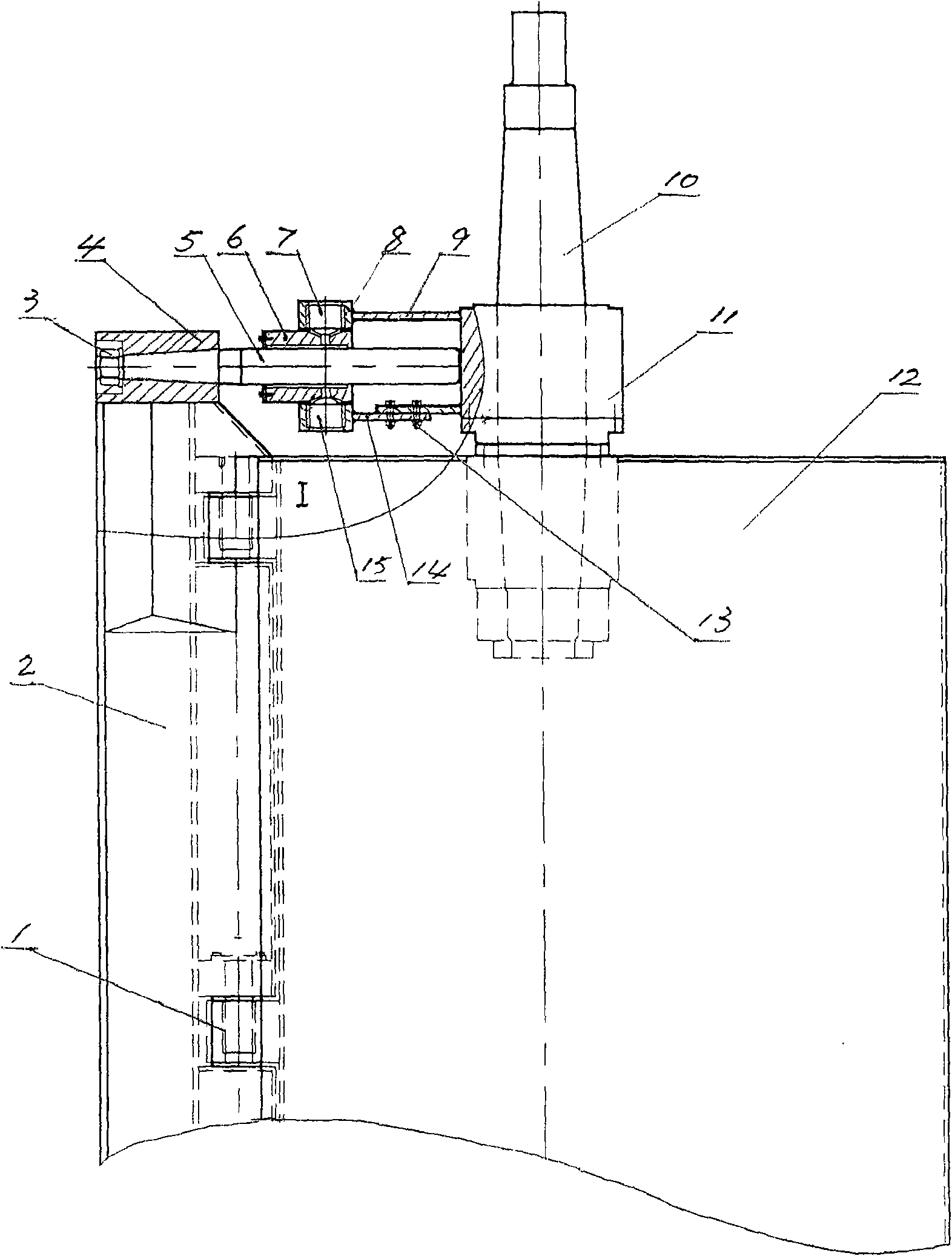
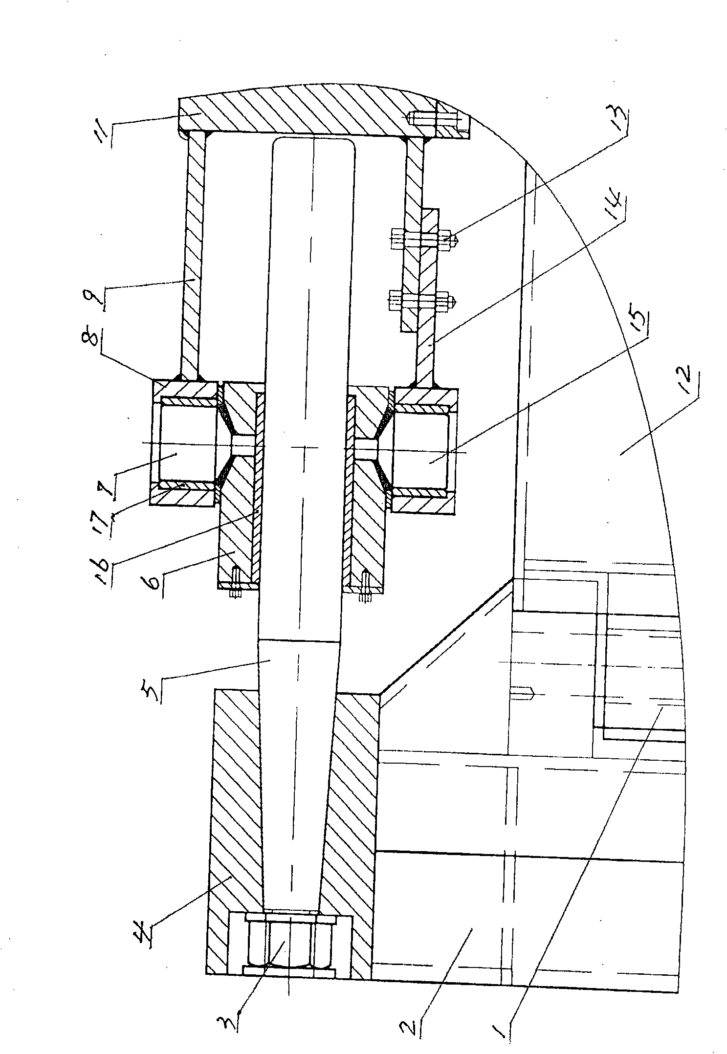
[0014] Such as figure 1 and figure 2 As shown, the flap rudder transmission device of the present invention contains a mother rudder 12 and a child rudder 2, and the longitudinal outer side of the mother rudder 12 and the longitudinal inner side of the child rudder 2 are hinged together by a pin seat 1 and a pin shaft, so that the mother rudder 12 and the child rudder are hinged together. The two rudders are hinged together in a parallel and rotating shape. The upper end of the mother rudder 12 is provided with a rudder stock 10 , and the lower end of the rudder stock 10 is fixedly connected with the mother rudder 12 . The outside of the rudder stock 10 is covered with a sleeve 11 and there is a movable fit between the two. A guide rod 5 is arranged between the upper end of the sub-rudder 2 and the sleeve 11, and a fixed block 4 is welded on the upper end of the sub-rudder 2. A tapered hole is processed on the fixing block 4 , and the tapered hole faces the sleeve 11 . Th...


PUM


Abstract

The invention relates to a flapped rudder transmission device. The device comprises a main rudder and an auxiliary rudder, wherein the main rudder and the auxiliary rudder are rotatably hinged together in parallel. The upper end of the main rudder is provided with a rudderstock, and the lower end of the rudderstock is fixedly connected with the main rudder. A sleeve barrel is arranged outside andis moveably matched with the rudderstock. The device is characterized in that the space between the upper end of the auxiliary rudder and the sleeve barrel is provided with a guide rod, the guide rodis horizontally arranged, the external end of the guide rod is fixed on the upper end of the auxiliary rudder, and the internal end points to the sleeve barrel. A sliding sleeve is arranged on the guide rod, and an upper connecting shaft and a lower connecting shaft are respectively fixed on the upper lateral face and the lower lateral face of the sliding sleeve. The upper connecting shaft and thelower connecting shaft are respectively provided with a bearing seat and a bearing, and the two bearing seats are respectively connected together with the sleeve barrel by an upper connecting plate and a lower connecting plate. The flapped rudder transmission device has long service life and higher rudder effect under small rudder angle, and is applicable to ships.

Description

technical field [0001] The invention relates to a transmission device. Specifically, it is the flap rudder drive on the ship. Background technique [0002] It is known in the shipbuilding industry that the traditional flap rudder transmission device includes a mother rudder and a child rudder, and the mother rudder and the child rudder are hinged together in a parallel and rotating manner. There is a rudder stock at the upper end of the mother rudder, and the lower end of the rudder stock is fixedly connected with the mother rudder. There is a sleeve outside the rudder stock and there is a movable fit between the two. The upper end of the rudder and the corresponding sleeve are respectively fixed with a small gear and a large gear, and the two gears are meshed together, and the transmission is carried out in the form of gear meshing. Due to the use of gear transmission, in order to avoid the corrosion of seawater on the gear, the gear is installed in a streamlined waterti...

Claims


Application Information

Patent Timeline
Patent Type & Authority Applications(China)
IPC IPC(8): B63H25/38B63H25/10
Inventor 吴朋朋阎辉潘道元高中学过志梅
Owner 戴三南
Why Eureka
Try Eureka