Dry-type cable terminal

A cable termination, dry technology

Active Publication Date: 2010-02-03
广东长牛电气股份有限公司
View PDF2 Cites 11 Cited by
  • Summary
  • Abstract
  • Description
  • Claims
  • Application Information

AI Technical Summary

Problems solved by technology

[0004] Therefore, the technical problem to be solved by the present invention is that the insulating part between the insulating sleeve and the stress control body of the dry-type cable terminal in the prior art is not set properly. To solve the problem of short service life of the cable terminal due to reasonableness, a dry type cable terminal with simple structure, maintenance-free and longer service life is provided

Method used


Image

  • Dry-type cable terminal
  • Dry-type cable terminal

Examples


Embodiment Construction

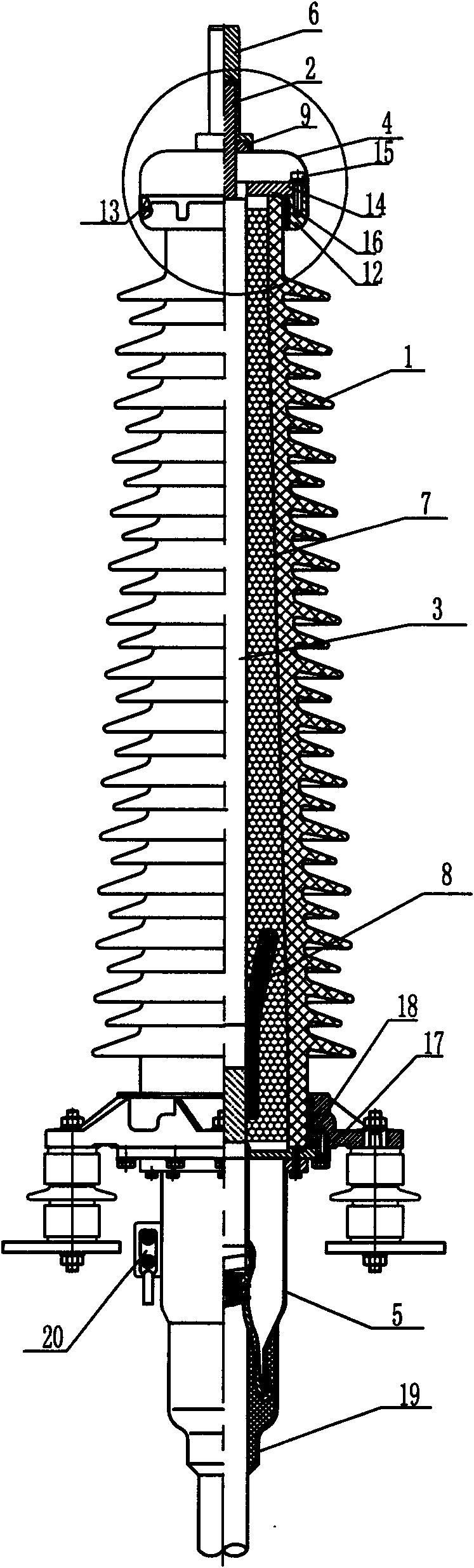
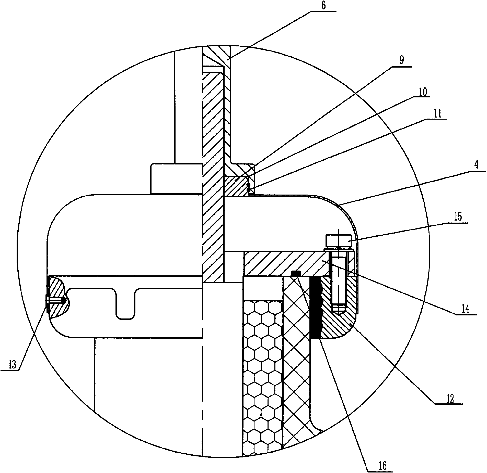
[0026] Such as figure 1 and figure 2As shown, a dry-type cable terminal of this embodiment, a dry-type cable terminal, includes an insulating sleeve 1 having an inner cavity 3 for the core wire 2 to pass through; it is arranged at the bottom of the insulating sleeve 1 The tail pipe 5 at the mouth of the nozzle for the core wire 2 to be inserted, the tail pipe 5 has a lower perforation for the core wire 2 to extend into the inner cavity 3; it is arranged on the top of the insulating sleeve 1 The shielding sealing cover 4 at the mouth of the tube for the core wire 2 to protrude from, the shielding sealing cover 4 is formed with an upper perforation for the core wire 2 to pass through the shielding sealing cover; and is arranged on the shielding sealing cover 4 On the sealing cover 4, the conductive rod 6 electrically connected to the end of the core wire 2 passing through the shielding sealing cover 4 is cylindrically formed on the inner wall of the insulating sleeve 1, and is...


PUM


Abstract

The invention relates to a dry-type cable terminal comprising an insulating sleeve, a tail pipe, a shielding sealing cover, a conducting rod and an insulating rubber layer. The insulating sleeve is provided with an inner cavity for core wires to pass through; the tail pipe at a pipe opening is arranged at the bottom of the insulating sleeve for core wires to insert in and provided with a lower perforation for the core wires to extend in the inner cavity; the shielding sealing cover at the pipe opening is arranged at the top of the insulating sleeve for the core wires to extend out; an upper perforation for the core wires to pass through the shielding sealing cover is formed on the shielding sealing cover; the conducting rod is arranged on the shielding sealing cover and electrically connected with the end part of the core wire passing from the shielding sealing cover; the insulating rubber layer is cylindrically formed on the inner wall of the insulating sleeve and fixedly connected with the inner wall of the insulating sleeve directly by the adhesiveness of the body; and a stress cone is embedded in the insulating rubber layer. The dry-type cable terminal has simple structure, maintenance free and longer service life.

Description

technical field [0001] The invention relates to the technical field of power cables, in particular to a dry-type cable terminal head. Background technique [0002] With the development of my country's electric power construction, the demand for electric power continues to rise, the demand for high-voltage power cables is increasing day by day, and the products of high-voltage cable accessories are also growing synchronously. The development and update of cable terminals for inter-connection is very rapid. Since the cable terminal plays a key role in the connection between the cable and electrical equipment such as transformers and distribution boxes, its excellent structure is directly related to the safe operation of the cable. Cause large-scale power outages, and cause losses to the lives and property of the country and the people. The traditional cable terminal head is an oil-filled terminal head, which uses insulating sleeves (such as porcelain tubes or silicone rubber ...

Claims


Application Information

Patent Timeline
Patent Type & Authority Applications(China)
IPC IPC(8): H02G15/06H02G15/064H02G15/068
Inventor 麦卓文李绍展李义敏
Owner 广东长牛电气股份有限公司
Why Eureka
Try Eureka