Eureka AIR delivers breakthrough ideas for toughest innovation challenges, trusted by R&D personnel around the world.

Measuring fixture

A jig and measurement technology, applied in optics, instruments, electrical components, etc., can solve the problems of electromagnetic interference, reduction of current RMS brightness value, increase of manufacturing cost, etc., to achieve the effect of eliminating electromagnetic interference

Inactive Publication Date: 2010-02-10
AU OPTRONICS (XIAMEN) CORP +1
View PDF0 Cites 4 Cited by
  • Summary
  • Abstract
  • Description
  • Claims
  • Application Information

AI Technical Summary

Problems solved by technology

This measurement fixture does not have the function of combing the wires. When performing optical performance measurement, it is easy to connect the AC output line of the drive circuit board and the balance board (Balance Board) and the DC input line for lighting the backlight module. Electromagnetic interference occurs due to being too close, which leads to a significant decrease in the effective value of the current and the measured luminance value of the two wires. Taking a 40-inch LCD TV panel as an example, the luminance reduction value due to electromagnetic interference exceeds 60 Candela per square meter (nit), which seriously affects the measurement results of optical properties
In addition, the original measurement fixture cannot be used in multiple product models due to the different shape of the drive circuit board. Generally, one model corresponds to one fixture, so the manufacturing cost will increase.

Method used


Image

  • Measuring fixture
  • Measuring fixture
  • Measuring fixture

Examples


Embodiment Construction

[0016] In order to have a further understanding of the purpose, structure, features, and functions of the present invention, the following detailed descriptions are provided in conjunction with the embodiments.

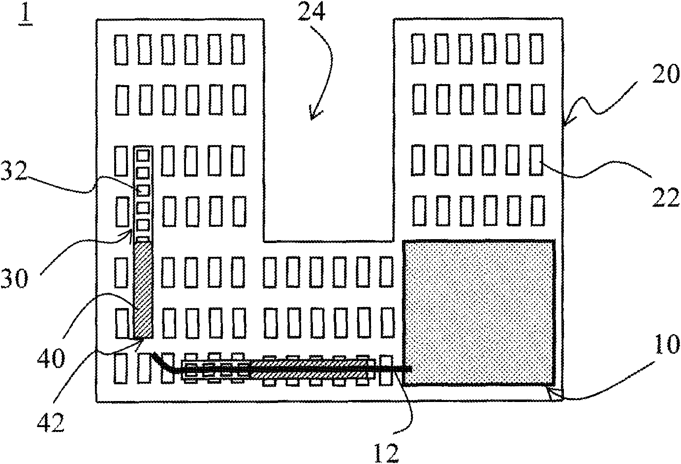
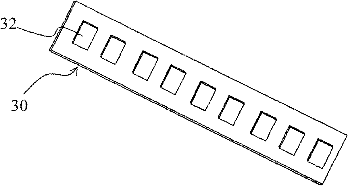
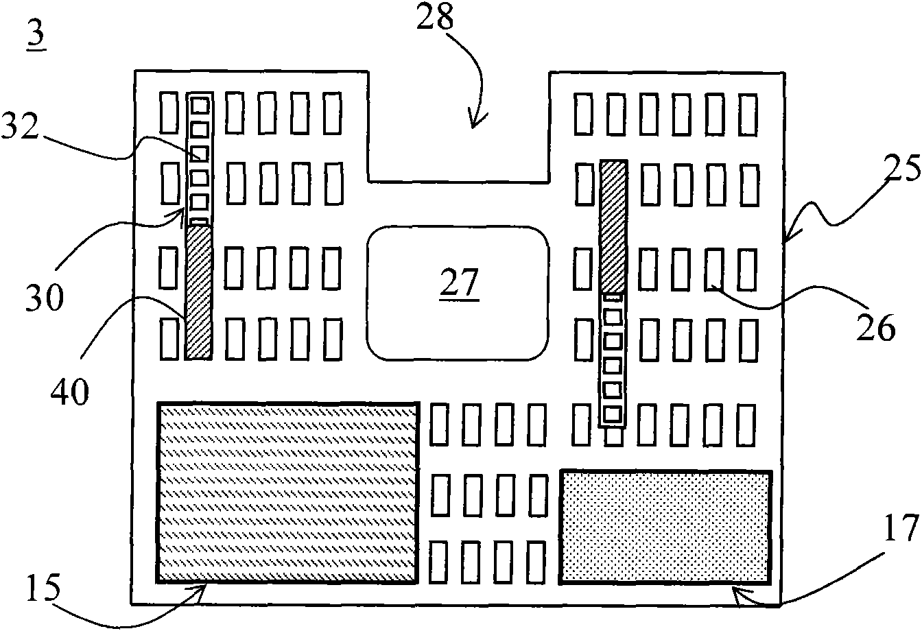
[0017] See figure 1 , figure 1 It is a schematic diagram of a measuring fixture 1 according to an embodiment of the present invention. The measuring jig 1 provided by the present invention is used to fix the circuit board 10 , and the measuring jig 1 includes a base frame 20 , a wiring board 30 and an electromagnetic shielding layer 40 . A plurality of positioning holes 22 are distributed on the surface of the base frame 20 . The cable management board 30 is disposed on the surface of the base frame 20 . The electromagnetic shielding layer 40 covers the cable management board 30 and forms a cable management channel 42 . Wherein, the circuit board 10 is fixed on the base frame 20 through the positioning hole 22 , and the circuit 12 connected with the circuit board ...


PUM


Abstract

The invention provides a measuring fixture which is used for fixing a circuit board; the measuring fixture comprises a base frame, a wiring plate and an electromagnetic shielding layer, wherein the surface of the base frame is distributed with a plurality of locating holes; the wiring plate is arranged on the base frame; the electromagnetic shielding layer covers the wiring plate, and a wiring channel can be formed. A circuit board is fixed on the base frame by the locating holes, and a circuit connected with the circuit board passes through the wiring channel. By adopting the measuring fixture, electromagnetic interference can be reduced when a liquid crystal display panel is tested, and the measuring fixture is applicable to multiple machines.

Description

technical field [0001] The present invention relates to a measuring fixture, in particular to a measuring fixture capable of eliminating electromagnetic interference and having the function of wire management. Background technique [0002] At present, when performing optical measurement on the LCD TV panel, the measurement fixture is often hung on the back of the LCD panel to fix the driving circuit board. This measurement fixture does not have the function of combing the wires. When performing optical performance measurement, it is easy to connect the AC output line of the drive circuit board and the balance board (Balance Board) and the DC input line for lighting the backlight module. Electromagnetic interference occurs due to being too close, which leads to a significant decrease in the effective value of the current and the measured luminance value of the two wires. Taking a 40-inch LCD TV panel as an example, the luminance reduction value due to electromagnetic interfer...

Claims


Application Information

Patent Timeline
Patent Type & Authority Applications(China)
IPC IPC(8): G02F1/13H05K9/00
Inventor 邱志斌林华星李建功
Owner AU OPTRONICS (XIAMEN) CORP
Why Eureka
Eureka Blog
Learn More