Hot rolling equipment and method for manufacturing steel product using the hot rolling equipment

A technology of equipment and hot rolling mills, applied in the direction of metal rolling, manufacturing tools, metal rolling, etc., can solve the problems of generating idle time and hindering rolling efficiency, etc.

Active Publication Date: 2010-02-10
JFE STEEL CORP
View PDF2 Cites 6 Cited by
  • Summary
  • Abstract
  • Description
  • Claims
  • Application Information

AI Technical Summary

Problems solved by technology

As a result, due to this waiting for cooling, there will be idle time in the hot

Method used


Image

  • Hot rolling equipment and method for manufacturing steel product using the hot rolling equipment
  • Hot rolling equipment and method for manufacturing steel product using the hot rolling equipment
  • Hot rolling equipment and method for manufacturing steel product using the hot rolling equipment

Examples


Embodiment Construction

[0076] One embodiment of the present invention will be described with reference to the drawings. In addition, the case where a rolling material is a steel material is demonstrated here as an example.

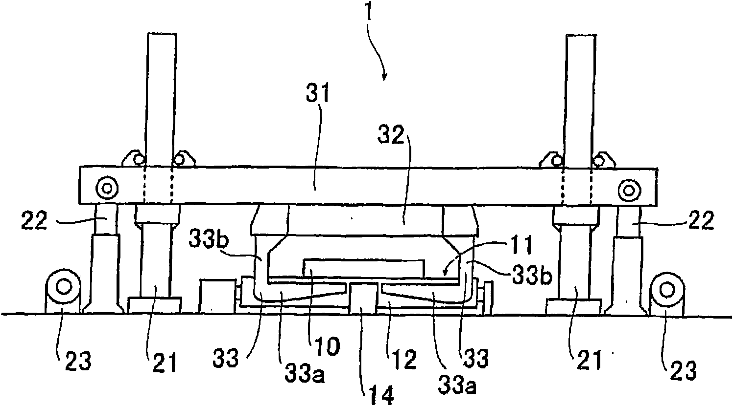
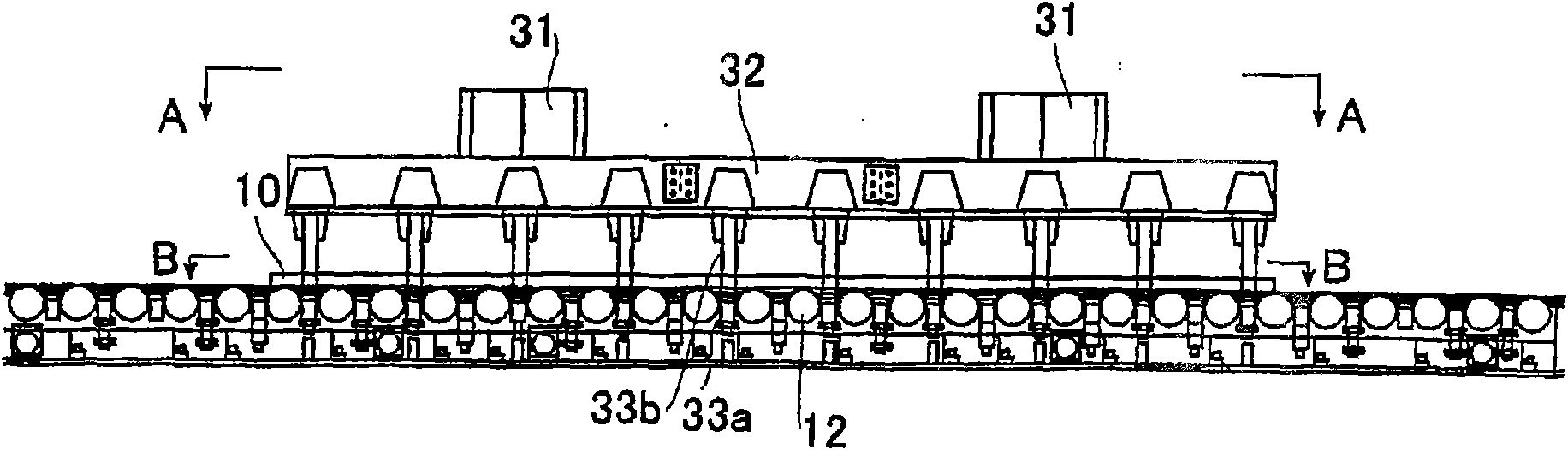
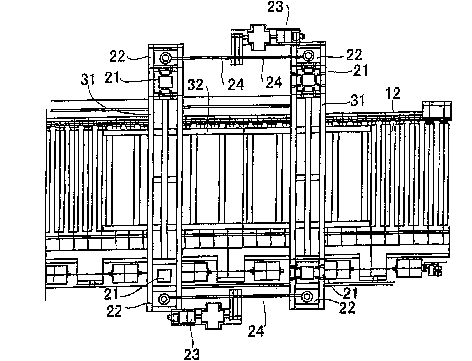
[0077] Figure 1 to Figure 4 A holding device for steel materials according to one embodiment of the present invention is shown. figure 1 main view, figure 2 for the side view, image 3 for figure 2 The diagram of the A-A arrow direction (top view), Figure 4 for figure 2 The diagram in the direction of the B-B arrow (top view).

[0078] Such as Figure 1 to Figure 4 As shown, the steel material holding device 1 according to this embodiment moves the steel material 10 on the conveying roller table (roller table) 11 to a position where the subsequent steel material can pass in hot rolling equipment such as a thick plate rolling equipment, And the holding device of the steel kept in standby state, it comprises: four pillars (support body) 21, are located at the both si...


PUM


Abstract

This invention provides a holding apparatus for lifting a rolling material on a transfer table to a height enough to allow a succeeding rolling material to pass through on the table, for example, forconducting passing rolling, in a hot rolling equipment, which apparatus can be installed without the need to ensure a wide space and can properly lift a rolling material. A steel product (10) is lifted while holding between both sides of the transfer table by a holding part (33a) in a plurality of sets of holding arms (33) mounted on frames (31, 32) which are lowered or lifted along four braces (21) provided on both sides of the transfer table (10). In the holding apparatus provided with the holding arm, the holding part in the holding arm has a proper heat insulating structure. There are alsoprovided a hot rolling equipment, which, even when a controlled rolling material for which waiting time for cooling is necessary is included, the idle time in a hot rolling machine can be reduced toimprove the rolling efficiency, and a hot rolling method using the hot rolling equipment.

Description

technical field [0001] The present invention relates to a hot rolling facility and a method for manufacturing steel using the hot rolling facility. Background technique [0002] For example, in heavy-plate rolling of steel materials, steel materials with excellent material quality are produced by performing controlled rolling (Controlled Rolling; CR). [0003] At this time, when the temperature at the time of controlled rolling (the controlled rolling start temperature) is low and the plate thickness at the time of the controlled rolling (the controlled rolling start plate thickness) is thick, the rolled material becomes the controlled rolling start temperature Since it takes quite a long time, the rolling material is made to wait until it reaches the controlled rolling start temperature on the conveyance roller table near the hot rolling mill. As a result, due to such waiting for cooling, idle time occurs in the hot rolling mill, and problems such as impairing rolling effi...

Claims


Application Information

Patent Timeline
IPC IPC(8): B21B39/00
CPCB21B39/00B21B1/34B21B45/02
Inventor 奥野昭博平田直人池田展也田中伦夫涩谷聪
Owner JFE STEEL CORP
Why Eureka
Try Eureka