Protective material having guard plates on clearly visible substrate
A guard plate and base fabric technology, applied in protective clothing, protective equipment, camouflage devices, etc., can solve problems such as incomplete fit
- Summary
- Abstract
- Description
- Claims
- Application Information
AI Technical Summary
Problems solved by technology
Method used
Image

Examples
Embodiment Construction
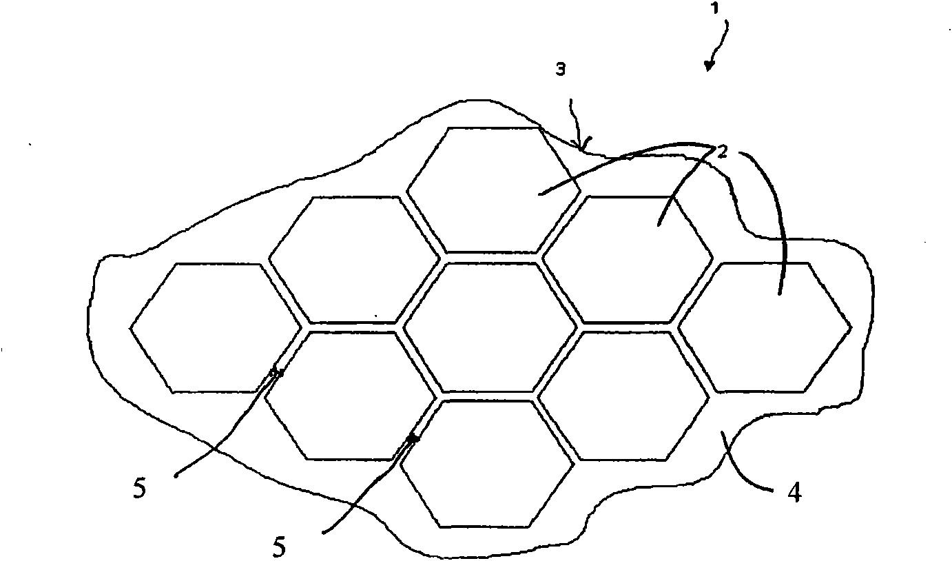
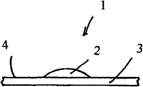
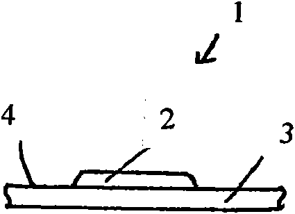
[0023] Figure 1 is a top view of a protective material 1 with a flexible base fabric 3 and spacer panels 2 according to one embodiment of the present invention. The fenders 2 are glued to the first or top surface 4 of the flexible base fabric 3, spaced apart from each other. In the embodiment shown in Fig. 1, the shields 2 are hexagonal in shape, arranged in a regularly repeating pattern. In some other embodiments, the guard plate 2 can be in other shapes, such as circular, square, or any other polygonal shape, and can be arranged in a random or irregular manner to fill the space. In one embodiment, the panels 2 are arranged in a mathematical Penrose tile form. The fenders 2 leave a gap width 5 between adjacent fenders 2 . In other embodiments, the panel 2 assembly includes a variety of different shapes (as shown in Figures 3-4). In the embodiment shown in Fig. 1B, the vertical section of the shield 2 is dome-shaped. In the embodiment shown in Fig. 1C, the vertical section...
PUM
 Abstract
Description
Claims
Application Information
 - Generate Ideas
- Intellectual Property
- Life Sciences
- Materials
- Tech Scout
- Unparalleled Data Quality
- Higher Quality Content
- 60% Fewer Hallucinations
Browse by: Latest US Patents, China's latest patents, Technical Efficacy Thesaurus, Application Domain, Technology Topic, Popular Technical Reports.
© 2025 PatSnap. All rights reserved.Legal|Privacy policy|Modern Slavery Act Transparency Statement|Sitemap|About US| Contact US: help@patsnap.com