Inductive power supply

a technology secondary coil, which is applied in the direction of inductance, transformer, poultry processing, etc., can solve the problems of limiting the use of inductive power supply, burdensome and aesthetically unpleasing, and limiting the interchangeability of multiple devices containing secondary coils, so as to reduce the footprint

Active Publication Date: 2013-02-12
PHILIPS IP VENTURES BV
View PDF21 Cites 122 Cited by
  • Summary
  • Abstract
  • Description
  • Claims
  • Application Information

AI Technical Summary

Benefits of technology

[0010]In a second aspect, the present invention provides a wireless power supply with a movable primary that allows for close alignment between the primary and the secondary when the remote device is disposed within a range of different positions with respect to the charging surface.
[0014]In a third aspect, the present invention provides a charging bowl having a plurality of charging stations disposed about a common axis. Each charging station may include an inclined charging surface that holds the remote device in an upright position and reduces the footprint that would be required to charge the same number of devices if positioned on a single plane.
[0015]In one embodiment, each charging station includes a movable primary that permit some freedom in positioning of the remote device on the charging surface. In one embodiment, the movable primary includes a plunger that mechanically couples the remote device to the primary so that the primary moves with the remote device along the charging surface. In an alternative embodiment, the movable primary and remote device include magnets that couple the primary and the remote device. The magnets may draw the primary into alignment with the secondary in the remote device and may keep the primary and secondary in alignment if the remote device is moved over the charging surface.
[0017]In one aspect, the present invention provides a simple and effective mechanical structure for assisting in improved alignment between the primary of a wireless power supply and the secondary of a remote device. In those embodiments that include an extendable plunger, the plunger may be retracted when not in use and therefore not interrupt the charging surface. This can be particularly beneficial when the charging surface is a desktop or other surface that may be used for other purposes when not charging. This is also beneficial when using devices that do not accept the movement of the plunger and can remain flush. In applications where the plunger engages magnetically but cannot move the inductive link is still very functional and the feedback to the user is very positive. This attribute allows these devices to be directly interchangeable except where movement engages the power supply. Other sensing and methods can be used for interoperable surfaces. The use of magnets to extend / retract the plunger is convenient and reliable because it requires no direct user interaction. In those embodiments in which the primary is disposed within the plunger, movement of the plunger can be used to provide improved coupling and therefore improved performance. Embodiments that use movement of the plunger to activate the power supply may provide reduced power consumption because they will poll for the remote device only when the plunger has been extended. The use of a moving primary coil provides the remote device with freedom of movement when it is on the charging surface. The mechanically coupling between the remote device and the primary coil (e.g. via the plunger) provides reliable physical movement of the primary coil. In another aspect, the present invention provides a charging bowl that permits wireless powering of multiple devices in a reduced footprint. The charging bowl includes inclined charging surfaces arranged around a common axis.

Problems solved by technology

Wired connections suffer from a variety of problems that make them inconvenient, burdensome and aesthetically unpleasing.
Perhaps most notably, wired connections require physically plugging and unplugging the device, involve a mess of unsightly cords, require matching plugs on the cord and remote device and can only charge a single device at a time with a single cord.
Although helpful in providing alignment, this approach requires deliberate placement of the remote device within the cradle and essentially precludes movement of the electronic device with respect to the power supply.
It may also limit the inductive power supply to use in connection with a single device specially configured to fit within the cup or cradle.
It also limits the ease of interchangeability with multiple devices containing secondary coils.
However, for other devices, it may provide a loose fit or a receptacle too small to allow any fit at all.
Although this construction provides good alignment between the electronic device and its matching wireless charger, it may suffer from a variety of issues.
For example, the peg is fixed and therefore does not provide any freedom of movement for the remote device.
Further, the fixed peg extends from the charging surface at all times (even when a remote device is not present), thereby interfering with use of the charging surface for other purposes.
Although providing some improvement, the force of the magnetic attraction may not be sufficient to move the primary magnet and primary coil within the void.
Further, because the primary magnet and primary coil are permitted to move freely within the void, their location may be unknown when initially placing the remote device on the charging surface.
This may make it more difficult to initially bring the two magnets together.

Method used


Image

  • Inductive power supply
  • Inductive power supply
  • Inductive power supply

Examples


Embodiment Construction

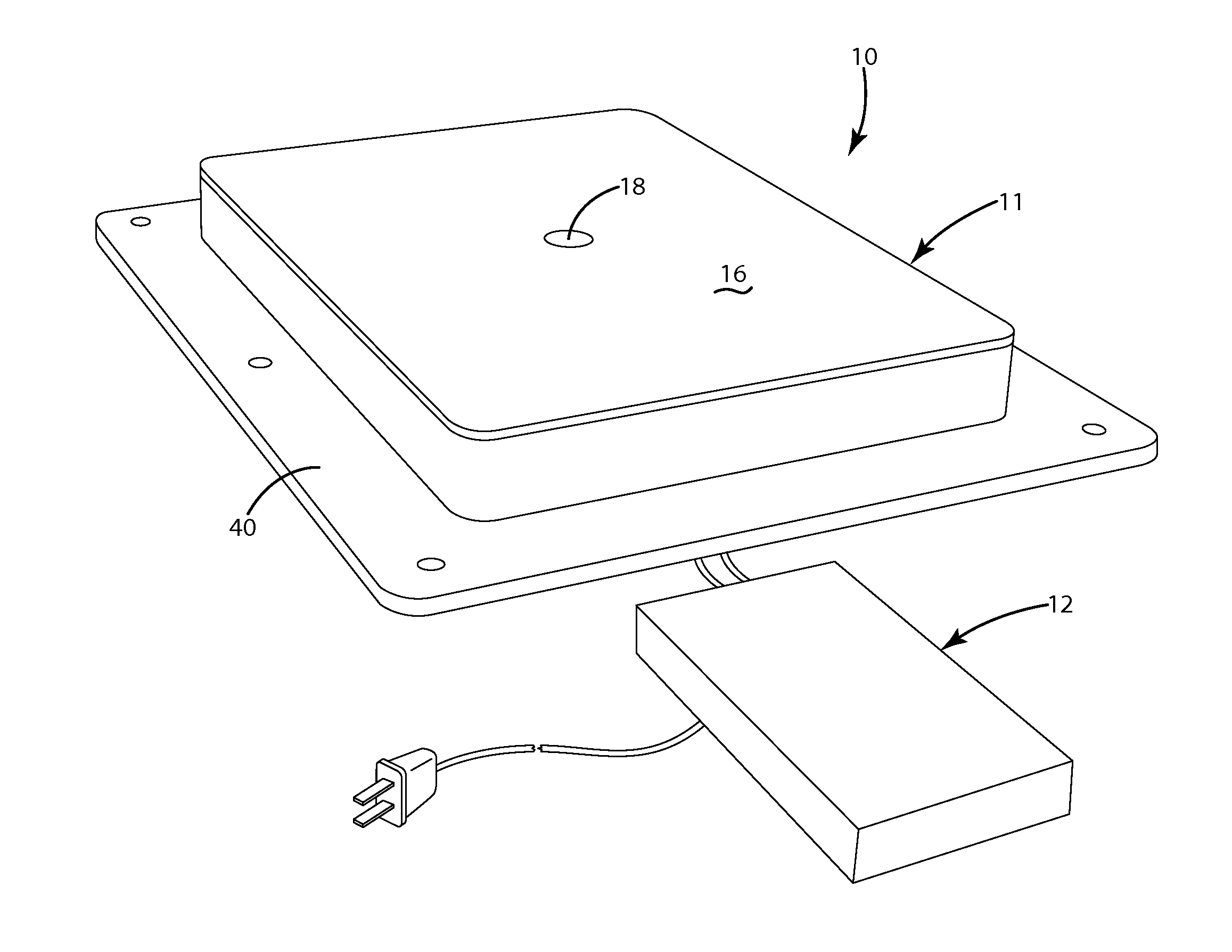
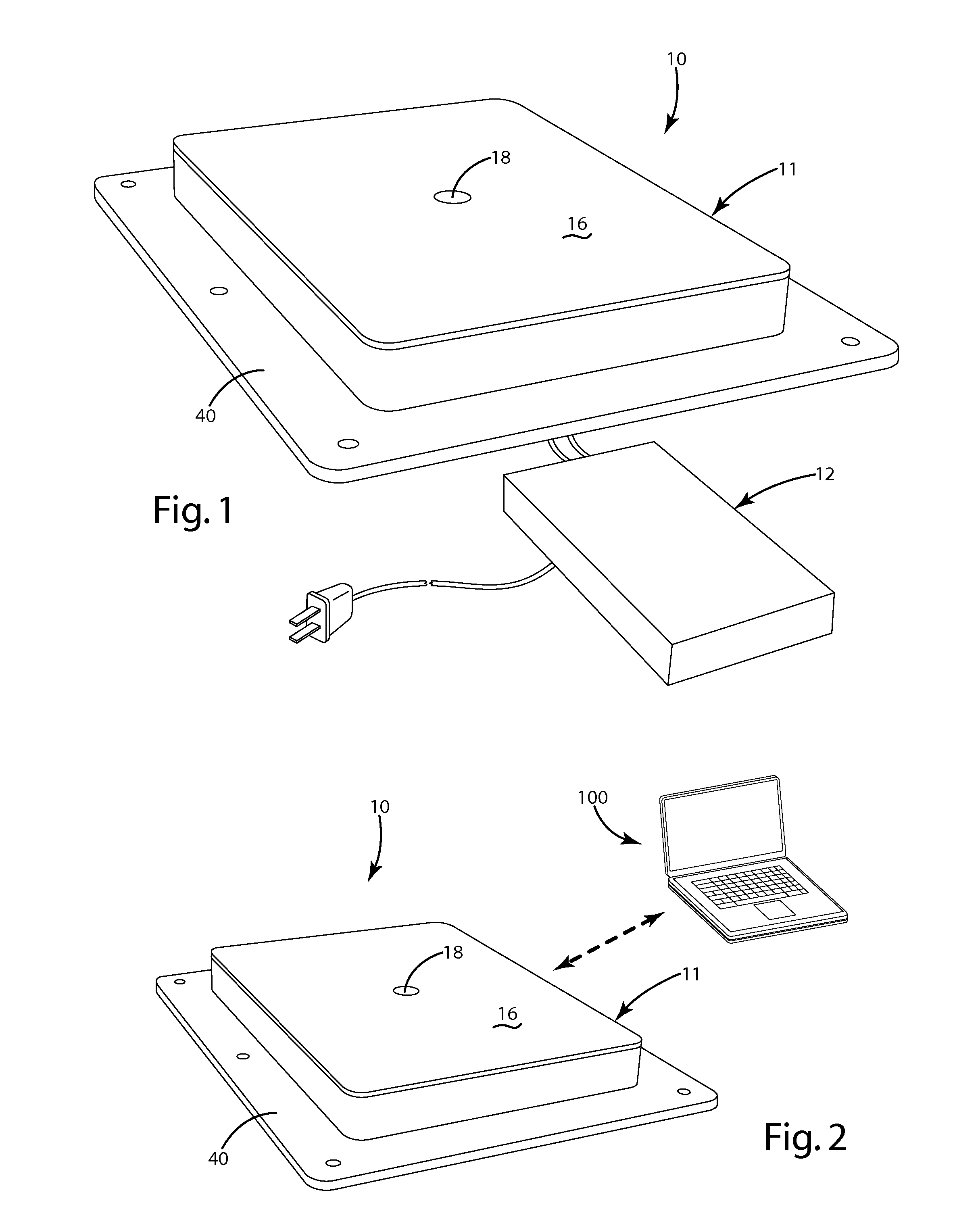
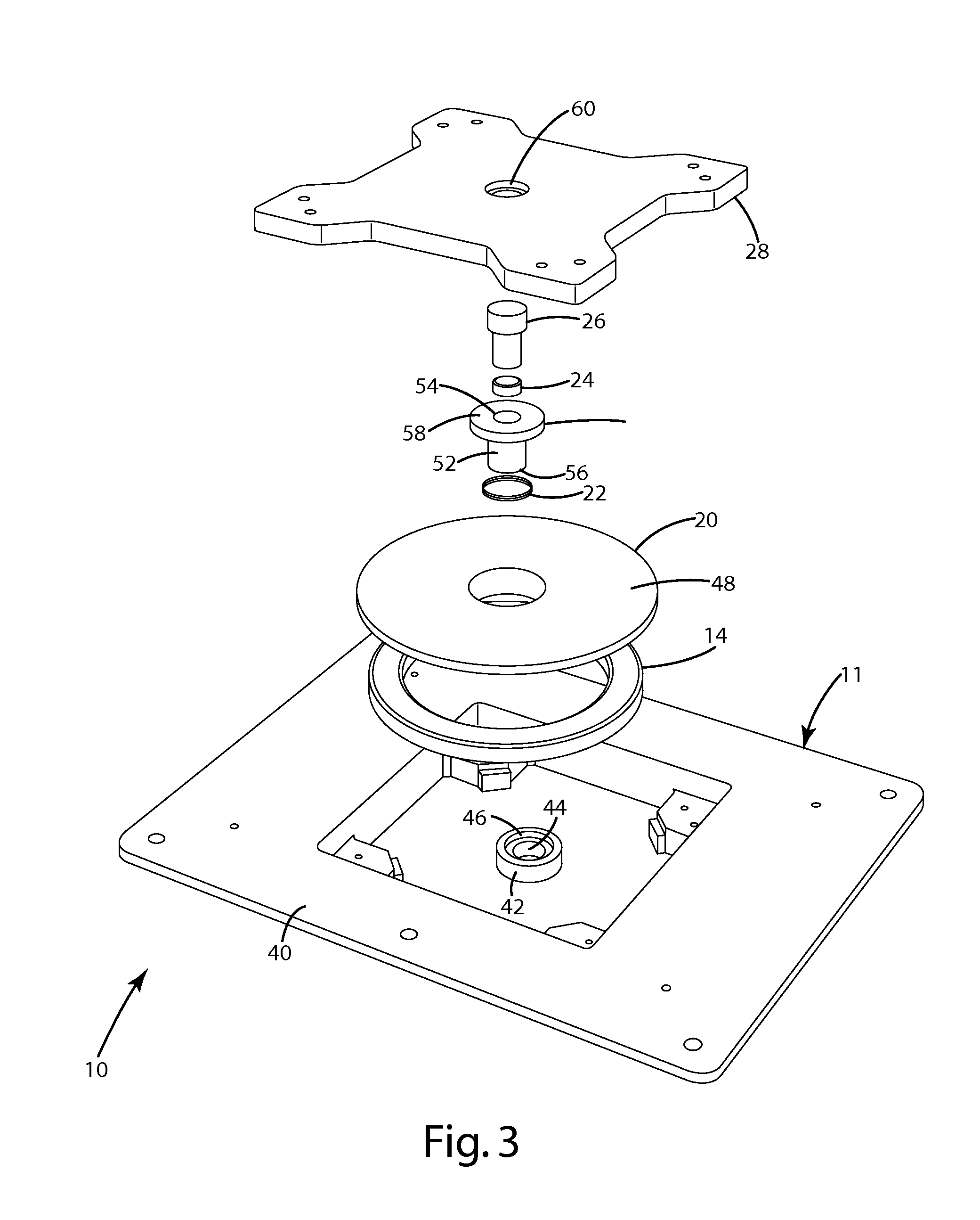
[0071]A wireless power supply 10 in accordance with an embodiment of the present invention is shown in FIG. 1. The wireless power supply 10 generally includes a housing 11 containing power supply circuitry 12, including a primary 14 for generating an inductive field. The housing 12 includes a charging surface 16 upon which a remote device, such as a portable electronic device (e.g. laptop 100), can be removably placed to receive wireless charging / power. The wireless power supply 10 includes a plunger 18 disposed in the charging surface 16. The plunger 18 is extendable / retractable with respect to the charging surface 16. The plunger 18 may be extended to provide a structure to mechanically interconnect with and align a remote device, and retracted to provide a generally flush charging surface 16 when no device is placed on the wireless power supply 10. The electronic device 100 may include a socket 106 adapted to interfit with the plunger 18 (See FIG. 5). In the illustrated embodimen...


PUM

PropertyMeasurementUnit
poweraaaaaaaaaa
electromagnetic fieldaaaaaaaaaa
movementaaaaaaaaaa

Abstract

In one aspect, the present invention provides a wireless power supply having a plunger for mechanically interconnecting a remote device with the power supply. The plunger may be extendable / retractable to interfit with the remote device. In a second aspect, the present invention provides a wireless power supply with a movable primary that allows for close alignment between the primary and the secondary when the remote device is disposed within a range of different positions with respect to the charging surface. The movable primary may, for example, be coupled to the remote device by a peg, a plunger or a magnet. Alternatively, the position of the movable primary may be adjusted manually. In a third aspect, the present invention provides a charging bowl having a plurality of charging stations disposed about a common axis. Each charging station may include a movable primary that permits some freedom in positioning of the remote device on the charging surface. In a fourth aspect, the present invention provides a wireless power supply having a manually movable primary.

Description

BACKGROUND OF THE INVENTION[0001]The present invention relates to wireless power supplies and more particularly to inductive power supplies.[0002]With the widespread and continually growing use of portable electronics, there is an ever-increasing need for wireless power supply system that are capable of charging and / or powering electronic devices without the need for direct wired connections. Wired connections suffer from a variety of problems that make them inconvenient, burdensome and aesthetically unpleasing. Perhaps most notably, wired connections require physically plugging and unplugging the device, involve a mess of unsightly cords, require matching plugs on the cord and remote device and can only charge a single device at a time with a single cord. Further, with conventional paired chargers, a user is required to keep and store as many wired DC power supplies as devices that are owned.[0003]Wireless power supply systems have proven to be a dramatic improvement over wired con...

Claims


Application Information

Patent Timeline
Patent Type & Authority Patents(United States)
IPC IPC(8): H01F27/42H01F37/00H01F38/00
CPCH01F38/14H02J17/00H02J7/025H02J7/0042H01F2038/143H02J50/80H02J50/40H02J50/10H02J50/70H02J50/005H02J50/402H02J7/0044G11B5/03H02J50/12H02J50/90
Inventor BAARMAN, DAVID W.STONER, JR., WILLIAM T.NORCONK, MATTHEW J.MOORE, COLIN J.SCHWANNECKE, JOSHUA K.LEPPIEN, THOMAS JAYWEBER, RICHARD J.SCHAMPER, RYAN D.
Owner PHILIPS IP VENTURES BV
Why Eureka
Try Eureka