Timing switching controller of double machines
A timing switching and controller technology, applied in the field of controllers, can solve the problems of poor stability, inconvenient use, complex structure, etc., and achieve the effects of high stability, practicability and versatility
Active Publication Date: 2011-06-15
GUANGDONG WESTINPOWER CO LTD
View PDF0 Cites 0 Cited by
- Summary
- Abstract
- Description
- Claims
- Application Information
AI Technical Summary
Problems solved by technology
[0002] In the prior art, machinery and equipment, such as generator sets, power devices, and some electronic automatic equipment, etc., are mainly controlled by relays for timing control of their working time and stop time, which has poor stability and complex structure, which brings many problems to the use. inconvenient
Method used
View moreImage
Smart ImageViewing Examples
Examples
Embodiment
[0019] Connecting the present invention to the working circuit of the generator set is used to realize the working time and switching setting of the two generator sets, and has the following characteristics and functions:
Login to View More PUM
 Abstract
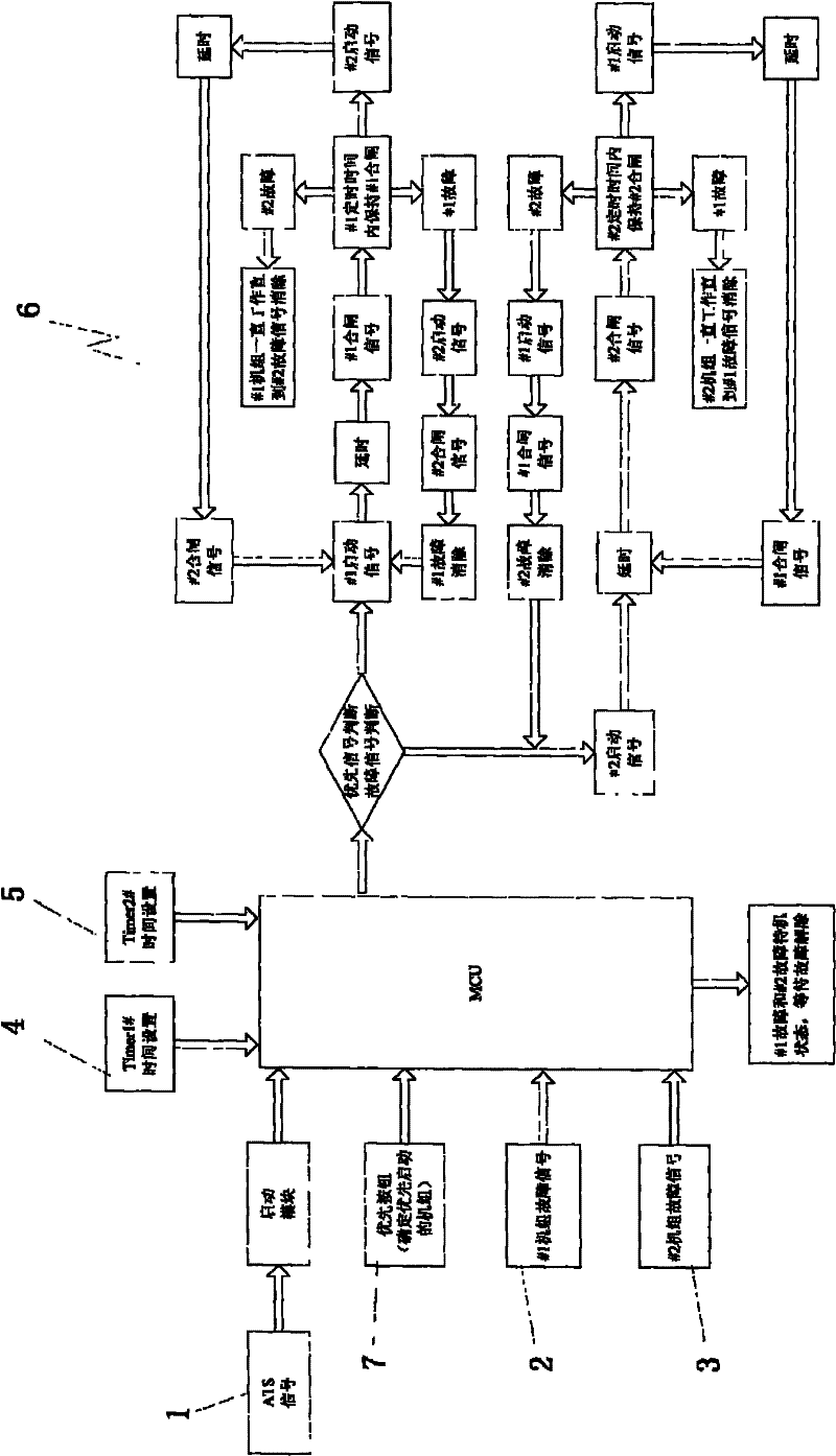
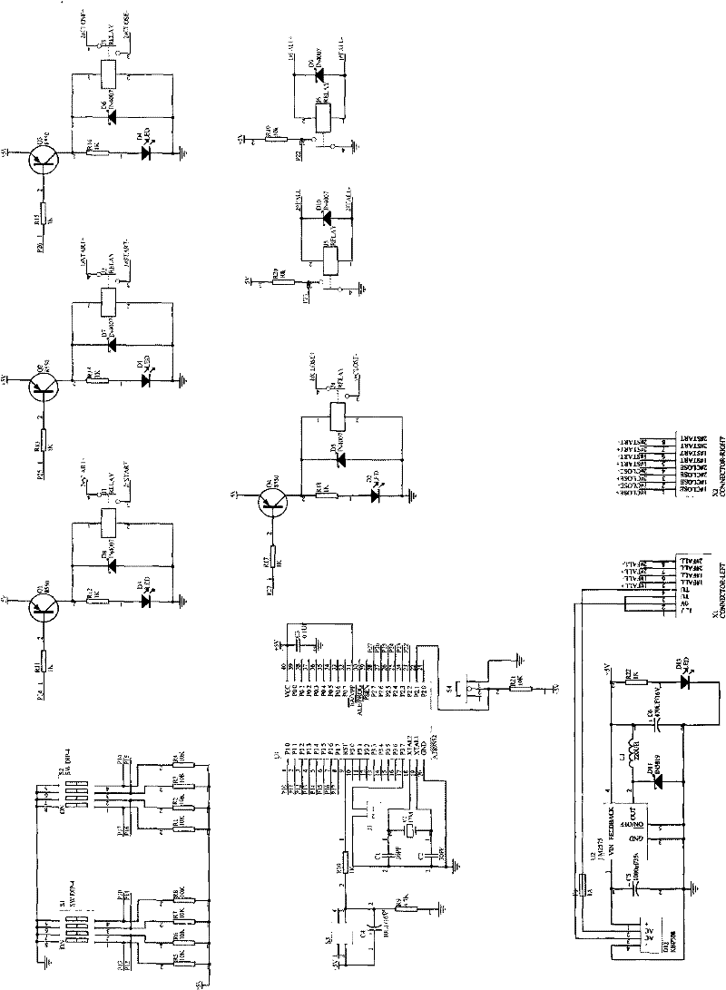
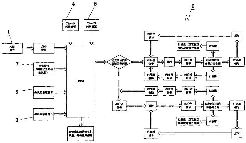
The invention relates to a timing controller for controlling the switching work of two pieces of machine equipment, which belongs to the technical field of controllers. The controller is characterized in that a singlechip MCU is used for logic control and is connected with a NO.1 machine signal driving unit, a failure signal unit, a NO.2 machine failure signal unit, a NO.1 machine time setting unit and a NO.2 machine time setting unit and the output end of the singlechip MCU is connected with an executing unit. The invention performs the logic control by adopting the singlechip MCU so as to realize programming control, can set the running time and the working sequence of the two pieces of machine equipment and has failure detecting function, can realize that the two machines can automatically work alternately according to the time set by a user with high control stability degree, and can be used in the condition of needing the two pieces of equipment to be switched by timing; and control logic can be modified according to a specific application with stronger practicability and universality.
Description
Technical field: [0001] The invention relates to the technical field of controllers, in particular to a timing controller for controlling the switching work of two machines and equipment. Background technique: [0002] In the prior art, machinery and equipment, such as generator sets, power devices, and some electronic automatic equipment, etc., are mainly controlled by relays for timing control of their working time and stop time, which has poor stability and complex structure, which brings many problems to the use. inconvenient. In this context, the applicant, in view of the lack and inconvenience of conventional timing controllers, upholds the spirit of research, innovation, and excellence, and uses his professional vision and expertise to develop a structure-optimized, performance-enhancing Two-machine timing switching controller. Invention content: [0003] The purpose of the present invention is to provide a dual-machine timing switching controller that can set the...
Claims
Login to View More Application Information
Patent Timeline
 Patent Type & Authority Patents(China)
IPC IPC(8): G05B19/042H05K5/00
Inventor 张婕张浴凯郑俊华翁镇波
Owner GUANGDONG WESTINPOWER CO LTD
Features
- R&D
- Intellectual Property
- Life Sciences
- Materials
- Tech Scout
- Unparalleled Data Quality
- Higher Quality Content
- 60% Fewer Hallucinations
Learn More Browse by: Latest US Patents, China's latest patents, Technical Efficacy Thesaurus, Application Domain, Technology Topic, Popular Technical Reports.
© 2025 PatSnap. All rights reserved.Legal|Privacy policy|Modern Slavery Act Transparency Statement|Sitemap|About US| Contact US: help@patsnap.com


