Apparatus for removing and polishing optical material, method of use and application thereof

An optical material and active reaction technology, applied in polishing devices and optical material removal fields, can solve the problems of narrow effective working range of working parameters, radio frequency electromagnetic pollution, and high processing cost, and can overcome sample surface and subsurface damage, and the scope of application Wide, high processing efficiency

Active Publication Date: 2015-10-21
XIAN TECH UNIV
View PDF1 Cites 0 Cited by
  • Summary
  • Abstract
  • Description
  • Claims
  • Application Information

AI Technical Summary

Problems solved by technology

[0004] 1. RF ion sources with a frequency above megahertz are often used, which is likely to cause radio frequency electromagnetic pollution
In addition, corresponding matchers need to be configured according to the specific ion torch device, gas source and gas distribution, and the effective working range of the working parameters is narrow, so the adaptability is poor;
[0005] 2. It is usually necessary to use more expensive helium as the plasma working gas, and in the atmospheric state, the gas consumption of the working gas is much higher than that in the vacuum state, so the processing cost is too high;
[0006] 3. Due to the sputtering effect of the plasma, in order to prevent the metal particles in the electrode from being excited to cause surface contamination, these low-temperature plasma methods usually use a water cooling device to cool the electrode, and limit its working power within a certain range, so that It leads to the complexity of the device structure and affects the processing efficiency
[0007] Therefore, the current atmospheric plasma processing technology still has various limitations in processing technology, processing efficiency and cost.

Method used


Image

  • Apparatus for removing and polishing optical material, method of use and application thereof
  • Apparatus for removing and polishing optical material, method of use and application thereof
  • Apparatus for removing and polishing optical material, method of use and application thereof

Examples


Embodiment 1

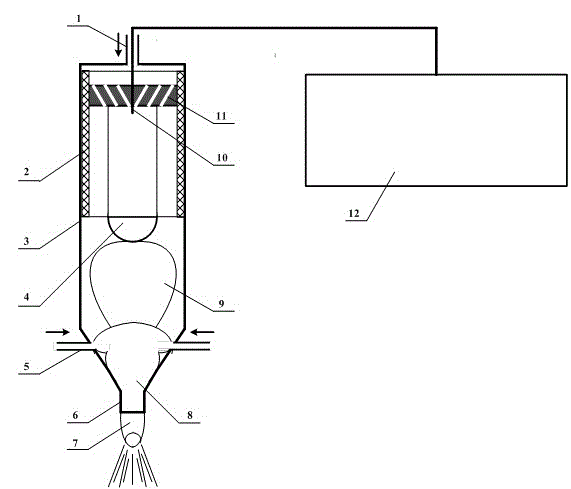
[0035] After the arc spindle-shaped nitrogen plasma area is formed, the active reaction gas inlet 5 at the side end of the spray gun is opened, and the sulfur hexafluoride gas enters the discharge channel at a pressure of 0.030Mpa. In this embodiment, the active gas inlets are set as two symmetrically distributed road. When SF 6 After entering, the ions in the nitrogen plasma area collide with it in a cascade, and under the action of high-energy nitrogen ions, the sulfur hexafluoride gas is ionized to form a secondary cascade collision plasma area containing a high concentration of active fluorine ions8 . Under the continuous pressure of the subsequent working gas, the generated cascade plasma region is constrained by the inverted trumpet-shaped jet nozzle 6 to form a jet flame 7 with a maximum diameter of 6-8mm. The mass is light, so it concentrates on the top of the flame body to form a blue fluoride ion region, and the blue fluoride ion region acts on the surface of optic...


PUM

PropertyMeasurementUnit
thicknessaaaaaaaaaa

Abstract

The invention relates to an optical machining device, in particular to a device for removing and polishing optical materials and an application method and applications thereof. The device comprises a housing composed of a stainless steel tube wall and an insulating ceramic bushing. Two ends of the housing are provided with a working gas inlet and a jet gun. An inner electrode is disposed inside the insulating ceramic bushing. A turbine gas circuit distributor is disposed inside the working gas inlet. The surface of the inner electrode is coated with a TiN coating. The stainless steel tube wall is made of 1Cr18Ni9Ti and is not smaller than 3mm in thickness. The turbine gas circuit distributor is made of dielectric ceramic. The part of the stainless steel tube wall, close to one end of the jet gun, is provided with evenly distributed active reactant gas inlets. The device is applicable to removing and polishing optical materials such as quartz and sapphire and is high in removal rate, low in machining cost, highly adaptable and convenient to industrially apply.

Description

technical field [0001] The invention relates to an optical processing device, in particular to a device for removing and polishing optical materials and its use method and application. Background technique [0002] Arc plasma technology is one of the mainstream technologies in the field of plasma applications. Because arc plasma equipment and technology are relatively simple, arc discharge energy is concentrated, and controllability is good, it is widely used in mechanical processing, metallurgy, chemical engineering, and environmental protection. field has been widely applied. However, because the arc plasma temperature is too high, it is easy to cause ablation on the processed surface. Therefore, although it has been used to melt high-purity quartz glass for a long time, it has not been used in the field of optical processing so far. [0003] At present, the ultra-smooth surface processing of large-caliber, high-precision and precision optical components has become an imp...

Claims


Application Information

Patent Timeline
Patent Type & Authority Patents(China)
IPC IPC(8): B24B1/00
Inventor 刘卫国惠迎雪杭凌侠朱学亮程媛郭忠达
Owner XIAN TECH UNIV
Why Eureka
Try Eureka