A Laser Damage Threshold Testing System

A technology of laser damage threshold and testing system, which is applied in the direction of testing optical performance, etc., can solve the problems of long time-consuming measurement process, large error, measurement error, etc., to overcome the strong subjectivity of measurement, overcome the large random error, and prevent measurement effect of error

Inactive Publication Date: 2016-01-20
XIAN TECH UNIV
View PDF8 Cites 0 Cited by
  • Summary
  • Abstract
  • Description
  • Claims
  • Application Information

AI Technical Summary

Problems solved by technology

[0006] 3. The manual detection method is inefficient, especially in the process of multi-point testing. In order to realize the focus positioning and measurement of each measurement point, the tester must have the skill of using the phase contrast microscope, so the measurement process is time-consuming. Long and unable to realize the automation of the whole machine
[0007] Therefore, the existing laser damage test method has caused a huge measurement error, and it is difficult to ensure high-precision measurement of the damage threshold of optical components or optical films.
In view of this, how to design an intelligent laser damage threshold testing system to effectively overcome the defects of large errors in existing measurement methods and long time-consuming measurement processes is an urgent task for relevant technical personnel.

Method used


Image

  • A Laser Damage Threshold Testing System

Examples


Embodiment 1

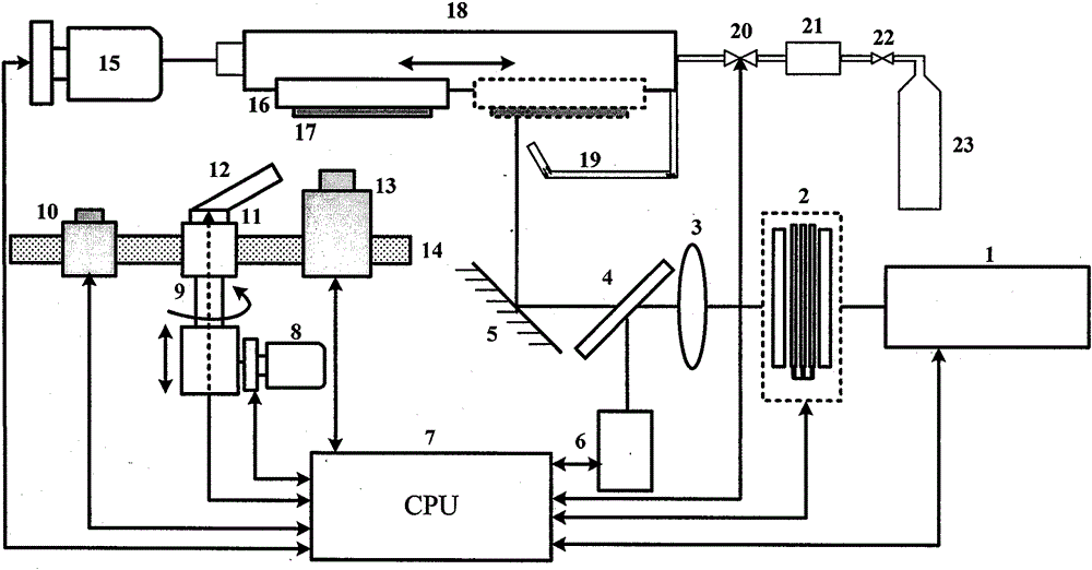
[0042] Such as figure 1 As shown, the high-energy laser (wavelength 1064nm, pulse width 12ns, single pulse energy can be adjusted in the range of 200mJ) emitted by Nd:YAG laser 1 passes through attenuator 2, focusing lens 3, beam splitter 4 and high reflector 5 converge on the sample to be tested. The output laser energy can be adjusted linearly within the range of 2-200mJ by using multiple sets of attenuation sheets combined with the attenuator 2 . Use a beam splitter to guide a small-energy laser into a laser test and analysis unit for energy beam analysis at a ratio of 100:1, and measure its parameters in real time.

[0043] According to the material properties of the test optical element or film sample, set the test laser energy range, and divide it into 10 equal parts, and irradiate 10 test points at each energy level in the order from high to low. Control the central processing unit 7 by programming, start the CCD clamping stage stepping drive motor and the sample stag...

Embodiment 2

[0046] Select the appropriate laser energy according to the specific conditions of the sample to be tested, such as figure 1 As shown, the software drives each console to adjust the focal length of the auxiliary light source and the CCD image acquisition unit. Use the same energy and the same time interval to perform multiple irradiation treatments on the same area of ​​the sample to be tested (the number of irradiations is set at 5 to 100 times), and at the same time as each irradiation, use a low-magnification CCD image acquisition unit to implement Observe the irradiation area of ​​the sample to be tested, stop the irradiation when obvious damage is found, and record the irradiation times as N. Drive the two-dimensional translation platform in the XY direction, move the irradiation area to another position, irradiate this area N-1 times with the same energy and the same time interval, and then switch the high-magnification CCD image acquisition unit to the observation posit...


PUM


Abstract

The invention provides a testing system for a laser induced damage threshold. The testing system for the laser induced damage threshold comprises a high-energy laser induced damage device, a high-resolution color CCD (charge coupled device) image damage judgment device, a CCD secondary light source device and a sample stage motion control device. According to the testing system for the laser induced damage threshold provided by the invention, initial and rapid damage prejudgment and accurate measurement are performed on a to-be-tested sample after being irradiated by high-energy laser successively by alternately adopting CCD acquisition units respectively provided with a low-power objective optical system and a high-power objective optical system. By adopting the testing system for the laser induced damage threshold provided by the invention, not only can the defects that the measurement subjectivity is strong, the measurement error is big and the measurement time is long by adopting a traditional phase contrast microscope method be effectively overcome, but also the requirements of two measurement patterns of 1-on-1 and R-on-1 can be met simultaneously, the measurement error and testing efficiency are both considered, the applicability is strong, and the industrial application is facilitated.

Description

technical field [0001] The invention relates to laser testing technology, in particular to a laser damage threshold testing system using phase contrast microscopy. Background technique [0002] With the continuous expansion of the application range of high-power lasers, the importance of the anti-laser damage performance of optical films or optical components has become increasingly prominent. Therefore, the laser damage threshold has become an indispensable performance index of optical films or optical components. To achieve high-performance, high laser damage threshold film preparation and research, the key is to accurately measure the laser damage threshold of optical components or films. Therefore, in the process of laser damage threshold testing, how to realize online, real-time, fast and accurate laser threshold damage discrimination, and on this basis, develop an intelligent laser threshold testing system with functions of automatic detection of laser threshold and da...

Claims


Application Information

Patent Timeline
Patent Type & Authority Patents(China)
IPC IPC(8): G01M11/02
Inventor 苏俊宏惠迎雪徐均琪李建超杨利红梁海锋朱昌
Owner XIAN TECH UNIV
Why Eureka
Try Eureka