Casing component embedded with antenna and manufacturing method thereof

The technology of a shell component and manufacturing method is applied to antenna parts, antennas, resonant antennas, etc., which can solve the problems of large internal space and low production efficiency of electronic devices, and achieve the goals of saving layout space, improving production efficiency, and enhancing strength Effect

Inactive Publication Date: 2010-02-17
SHENZHEN FUTAIHONG PRECISION IND CO LTD +1
View PDF0 Cites 55 Cited by
  • Summary
  • Abstract
  • Description
  • Claims
  • Application Information

AI Technical Summary

Problems solved by technology

However, this kind of antenna structure occupies a large internal space of the electronic device, and it is fixed on the main circuit board by adhesive tape or hot melt. It requires operators to work one by one, and the production efficiency is low.

Method used


Image

  • Casing component embedded with antenna and manufacturing method thereof
  • Casing component embedded with antenna and manufacturing method thereof
  • Casing component embedded with antenna and manufacturing method thereof

Examples


Embodiment Construction

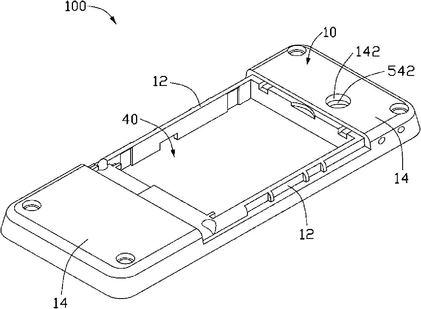
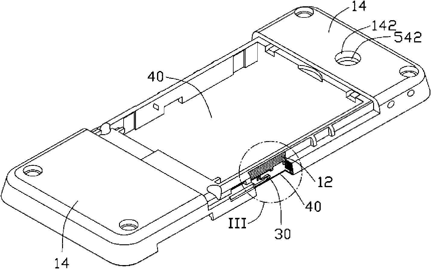
[0018] see figure 1 , figure 2 and image 3 , the housing assembly 100 of the built-in antenna in the preferred embodiment of the present invention includes a housing 10 , an antenna body 20 , a connecting body 30 and a circuit board 40 . The antenna body 20 is embedded in the casing 10 and is electrically connected to the circuit board 40 through the connecting body 30 .

[0019] The housing 10 is a frame made of plastic material, which includes two opposite first side walls 12 and two opposite end portions 14 . A blind hole 142 is formed on one end portion 14, and the blind hole 142 is a round hole.

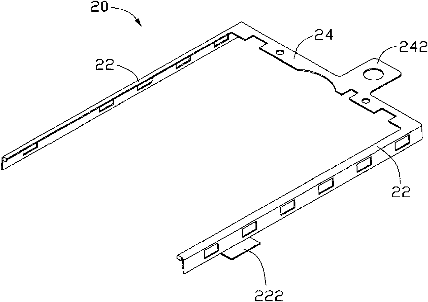
[0020] The antenna body 20 is substantially a “U”-shaped frame, which includes two opposite antenna arms 22 and a connecting arm 24 connecting the two antenna arms 22 . The outer side of each antenna arm 22 is formed with an electrical connection portion 222 electrically connected to the circuit board 40 through the connecting body 30. One side of the connecting arm 24 is ...


PUM


Abstract

The invention provides a casing component embedded with an antenna and a manufacturing method thereof. The casing component comprises an antenna body, a casing and a circuit board; the antenna body comprises an electrical connection part; the antenna body is subject to embedded injection to be embedded into the casing and exposed out of the electrical connection part; and the electrical connectionpart and the circuit board are communicated electrically. The antenna structure is manufactured by adopting an embedded shaping manner, and the casing component can reduce inner room of an electronicdevice and improve production efficiency.

Description

technical field [0001] The invention relates to a casing component with an antenna inside and a manufacturing method of the casing component. Background technique [0002] Electronic communication devices generally receive or transmit various instant information through radio waves, so in such devices, antennas undoubtedly become one of the most important components in electronic devices. [0003] Existing electronic communication devices are designed to be easy to carry by users, and their fuselages are designed to be light, thin, and short. Therefore, the space for the antenna to be installed inside the fuselage is gradually limited, and it can neither take up too much space nor be too large. Reduce the size of the antenna itself, otherwise the communication effect of the electronic device will be reduced. Existing antennas are generally stamped from copper or aluminum plates, which are fixed to the main circuit board inside the electronic device by tape or hot melt, and ...

Claims


Application Information

Patent Timeline
Patent Type & Authority Applications(China)
IPC IPC(8): H05K5/00H05K5/02H01Q1/22H01Q1/38H01Q9/04H01R4/48B29C70/68B29K705/00B29L12/00
CPCB29C45/14065B29L2031/3481B29L2031/3456B29C45/14639H01Q1/40H01Q1/243H04M1/0202B29L2031/3431H01Q1/44B29L2031/3437
Inventor 陈信驿赵元孝
Owner SHENZHEN FUTAIHONG PRECISION IND CO LTD
Why Eureka
Try Eureka