Self-priming vane pump

A vane pump, self-priming technology, applied in the direction of rotary piston pumps, pumps, pump components, etc., can solve the problems of long time, low running speed, low sealing quality, etc.

Inactive Publication Date: 2010-02-24
GM GLOBAL TECH OPERATIONS LLC
View PDF0 Cites 6 Cited by
  • Summary
  • Abstract
  • Description
  • Claims
  • Application Information

AI Technical Summary

Problems solved by technology

Since at start-up, the pump is usually running at low speed and zero pressure, the seal quality is low and this problem is exacerbated by the inactive state of the pump so that the formation of the active and the delivery of the pressurized fluid can take an undesirably long time

Method used


Image

  • Self-priming vane pump
  • Self-priming vane pump
  • Self-priming vane pump

Examples


Embodiment Construction

[0020] The following description is merely exemplary in nature and does not limit the disclosure and its application or uses.

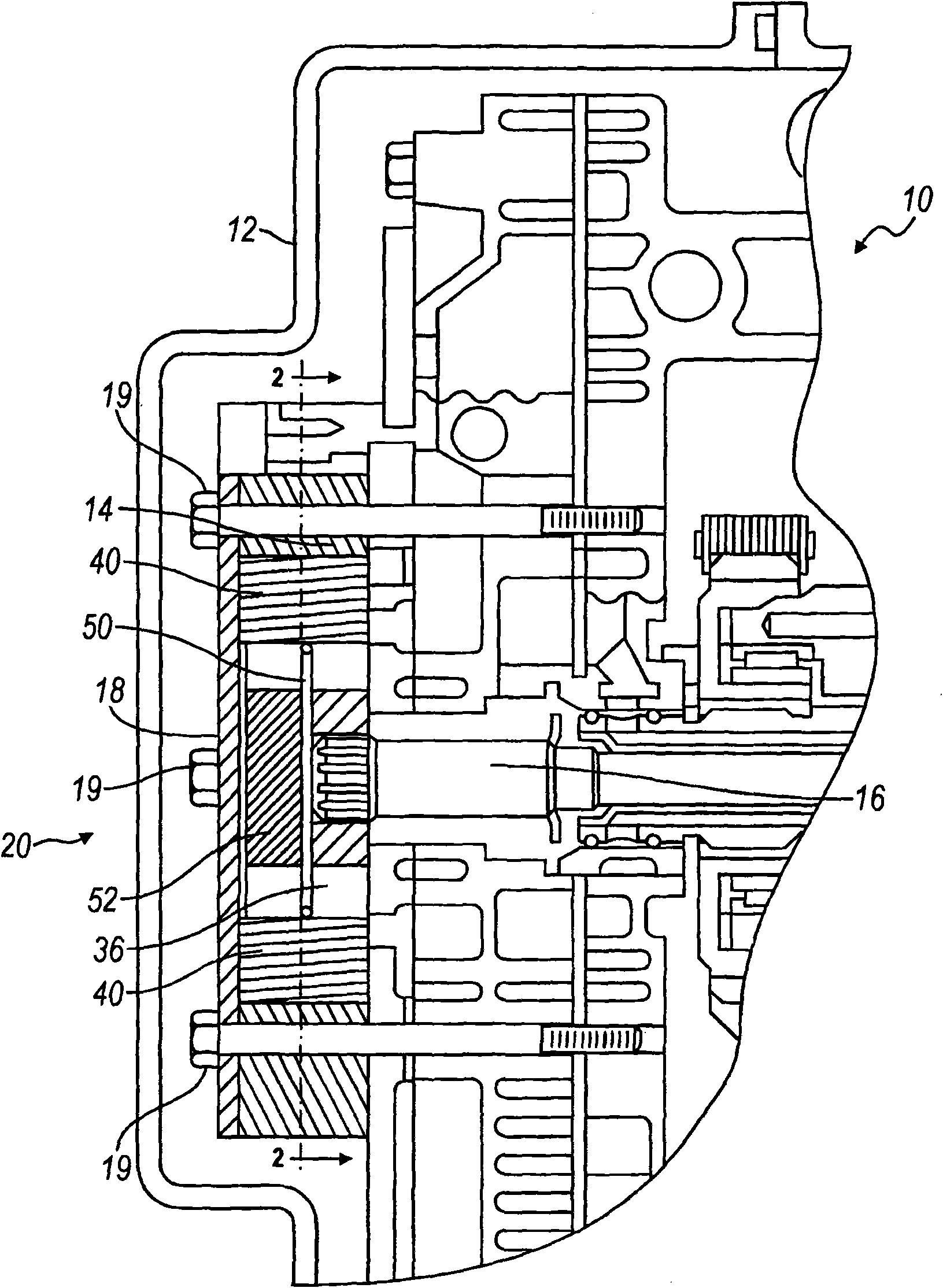
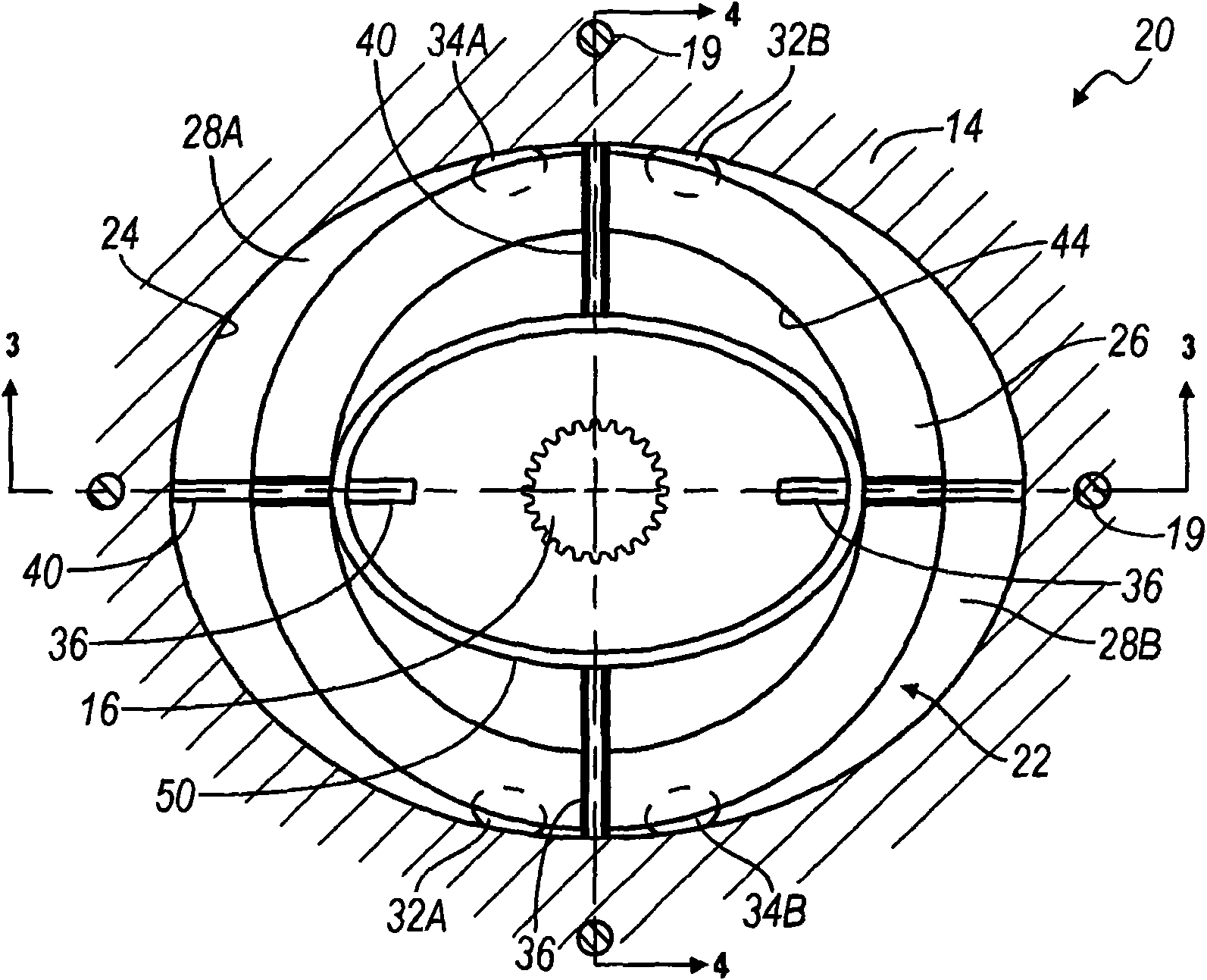
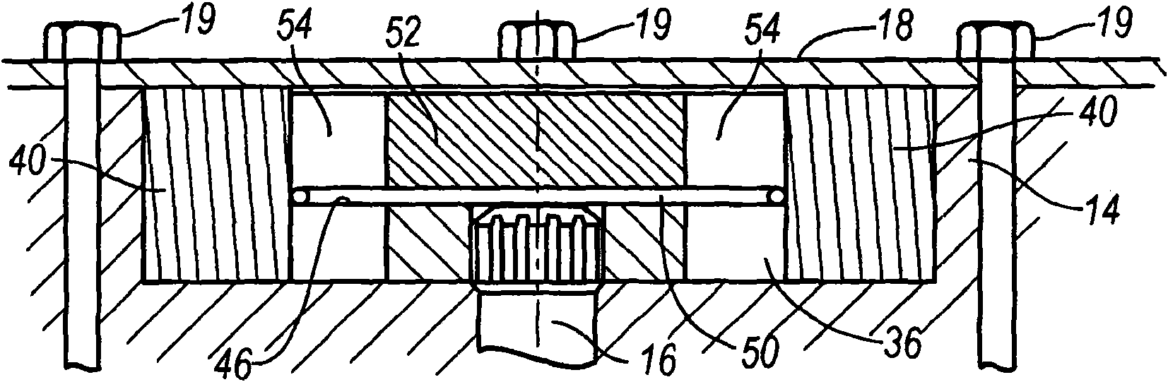
[0021] refer to figure 1 , shows a portion of an automatic transmission incorporating the present invention, generally indicated by reference numeral 10 . The automatic transmission 10 includes a housing 12, figure 1 Part of it is shown in . Housing 12 encloses and protects various components of automatic transmission 10 , such as vane pump housing 14 and drive shaft 16 supported in vane pump housing 14 . A front plate 18 , held by suitable fasteners such as bolts 19 , closes the front side of the vane pump housing 14 . Drive shaft 16 drives a vane pump 20 incorporating the present invention. Vane pump 20 draws hydraulic fluid or oil from an oil sump (not shown) in transmission housing 12 and provides this hydraulic fluid or oil under pressure to various control circuits and devices (not shown) of automatic transmission 10 . ) and bearings, clutc...


PUM


Abstract

A self-priming vane pump includes a cylindrical rotor disposed in a cavity in a housing including inlet and outlet ports. The rotor defines a plurality of axially extending slots which each receive one of a like plurality of vanes. A garter spring or similar resilient annulus is disposed within the rotor and provides a radially outwardly directed force on the vanes which maintains their contact with the cavity walls during pump start-up and rapidly self-primes the pump. The spring or annulus rests against a shoulder within the hollow rotor and is retained therein by a pressed in collar.

Description

technical field [0001] The present disclosure relates to vane pumps, and more particularly to self-priming vane pumps. Background technique [0002] The content in this part is only to provide background technology related to the present disclosure, which may or may not constitute prior art. [0003] Gear pumps and rotary pumps are often the preferred choice for fixed or positive displacement pumps in applications requiring flows and pressures down to normal averages. However, one disadvantage of such pumps is their efficiency. Due to their construction, when they operate, there will be backflow or leakage through the meshing rotors and around the rotor tips, resulting in reduced forward flow and thus reduced pumping efficiency. [0004] Fixed displacement vane pumps perform at the same flow and pressure range, exhibiting increased efficiency due to reduced leakage and backflow. This reduction in leakage and backflow is achieved due to a better seal between the outer edge...

Claims


Application Information

Patent Timeline
Patent Type & Authority Applications(China)
IPC IPC(8): F04C2/344
CPCF04C2/3446F04C2240/20F01C21/0845
Inventor S·P·穆尔曼
Owner GM GLOBAL TECH OPERATIONS LLC
Why Eureka
Try Eureka