Flat plate solar heat collector

A solar heat collector, a flat-plate technology, applied in the field of solar heat collectors, can solve the problems of poor joints of heat collectors, expensive plate cores, poor heat collection effects, etc., and achieve good heat collection effects, simple structure, The effect of strong pressure resistance

Inactive Publication Date: 2010-02-24
宋武先
View PDF0 Cites 7 Cited by
  • Summary
  • Abstract
  • Description
  • Claims
  • Application Information

AI Technical Summary

Problems solved by technology

[0003] The purpose of the present invention is to solve the problem that the plate core of the existing solar heat collector is expensive, the heat collection effect is poor, and the existing heat collector wastes a lot of heat energy due to the lack of joint, and then provides a flat plate type solar collector

Method used


Image

  • Flat plate solar heat collector
  • Flat plate solar heat collector

Examples


specific Embodiment approach 1

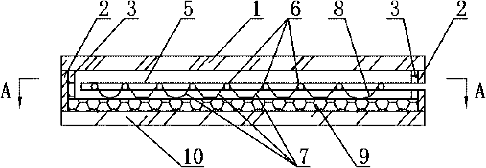
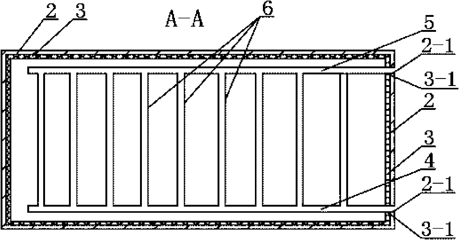
[0007] Specific implementation mode one: as figure 1 with 2 As shown, the flat-plate solar collector described in this embodiment includes a cover plate 1, a rectangular frame 2, a frame insulation layer 3, a water inlet pipe 4, an outlet pipe 5, a plurality of stainless steel pipes 6, a heat-absorbing coating 8, and a thermal insulation layer. Layer 9 and bottom plate 10, the heat collector also includes a plurality of heat collecting plates 7, the rectangular frame 2 is fixed horizontally on the upper end surface of the bottom plate 10, and the inner wall around the rectangular frame 2 is provided with a frame insulation layer 3, The insulation layer 9 is arranged on the upper end surface of the bottom plate 10 and is located in the rectangular frame 2, the water inlet pipe 4 and the water outlet pipe 5 are arranged in the rectangular frame 2 along the length direction of the rectangular frame 2, and a plurality of stainless steel pipes 6 are arranged in parallel on the wate...

specific Embodiment approach 2

[0008] Specific implementation mode two: as figure 1 with 2 As shown, the heat-absorbing coating 8 in this embodiment is a black chrome coating. Such setting can make the heat collecting plate absorb more heat energy. Other components and connections are the same as those in the first embodiment.

specific Embodiment approach 3

[0009] Specific implementation mode three: as figure 1 with 2 As shown, the water inlet pipe 4 and the water outlet pipe 5 in this embodiment are all stainless steel pipes. Stainless steel tubes are used for good heat transfer performance. Other compositions and connections are the same as those in Embodiment 1 or 2.


PUM


Abstract

The invention relates to a heat collector, in particular to a flat plate solar heat collector, solving the problems of high plate core price, poor heat collection effect of the prior solar collector and great heat energy waste due to the loose joint of the prior collector. A frame insulation layer is arranged on a peripheral inner wall of a rectangular frame and arranged on the upper end surface of a soleplate in the rectangular frame; water inlet pipes and water outlet pipes are arranged in the rectangular frame along the length direction; a plurality of stainless steel pipes are arranged inparallel between the water inlet pipes and the water outlet pipes; one end of each stainless steel pipe is communicated with a water inlet pipe, and the other end of each stainless steel pipe is communicated with a water outlet pipe; a heat-collecting plate is fixedly mounted between two adjacent stainless steel pipes; and a heat-absorbing coating is coated on the upper surface of the heat-collecting plate which has an arc cross section. The collector plate has large heat-absorbing area and good collection effect and improves the heat energy utilization due to the arc cross section. The invention also has the advantages of simple structure, reliable operation, low cost, and the like.

Description

technical field [0001] The invention relates to a solar heat collector. Background technique [0002] Solar energy is an inexhaustible clean energy. Under the premise of today's increasingly tense energy sources, the widespread application of solar energy has attracted widespread attention. Solar collectors are constantly developing in our country. At present, there are two main forms of commonly used products: 1. Vacuum glass tube type; 2. Copper-aluminum composite tube-sheet type. However, the solar heat collectors of the above two forms have the following disadvantages: one, the core of the solar heat collector is expensive, and the heat collection effect is poor; two, the existing heat collectors waste a large amount of heat energy due to loose joints. Contents of the invention [0003] The purpose of the present invention is to solve the problem that the plate core of the existing solar heat collector is expensive, the heat collection effect is poor, and the existing...

Claims


Application Information

Patent Timeline
Patent Type & Authority Applications(China)
IPC IPC(8): F24J2/24F24J2/48F24J2/46F24S10/70
CPCY02E10/44
Inventor 宋武先
Owner 宋武先
Why Eureka
Try Eureka