Heat exchanger structure

A heat exchanger and heat transfer medium technology, applied in water heaters, fluid heaters, lighting and heating equipment, etc., can solve the problems of reduced service life of plate heat exchangers, large system resistance, and less effective heat energy, and achieve improved Effect of heat conversion efficiency, improvement of heat conversion coefficient, and prolongation of service life

Active Publication Date: 2010-12-29
WUXI XIZHOU MACHINERY
View PDF2 Cites 7 Cited by
  • Summary
  • Abstract
  • Description
  • Claims
  • Application Information

AI Technical Summary

Problems solved by technology

At present, the heat transfer efficiency of heat exchangers on the market is generally between 75% and 90%, and its heat transfer efficiency cannot meet the current needs of energy saving and environmental protection; secondly, the composition and structure of heat exchangers are complex, and the heat loss in the middle is large , the available effective heat energy is less, so the heat conversion efficiency is low; because the heat transfer medium flows through the heat exchanger pipe or switch, it is often laminar flow instead of turbulent flow, and because a large amount of fine-crystalline alkali is entrained in the fluid, the plate heat transfer The scarring and silting of the heat exchanger is very serious, resulting in large system resistance and low heat transfer efficiency; the heat exchanger heat exchanger has a large workload of pickling, maintenance, and cleaning, and the maintenance cost is high; due to severe fluid corrosion and erosion, the service life of the plate heat exchanger is reduced

Method used


Image

  • Heat exchanger structure
  • Heat exchanger structure
  • Heat exchanger structure

Examples


Embodiment Construction

[0011] The present invention will be further described below in conjunction with specific drawings and embodiments.

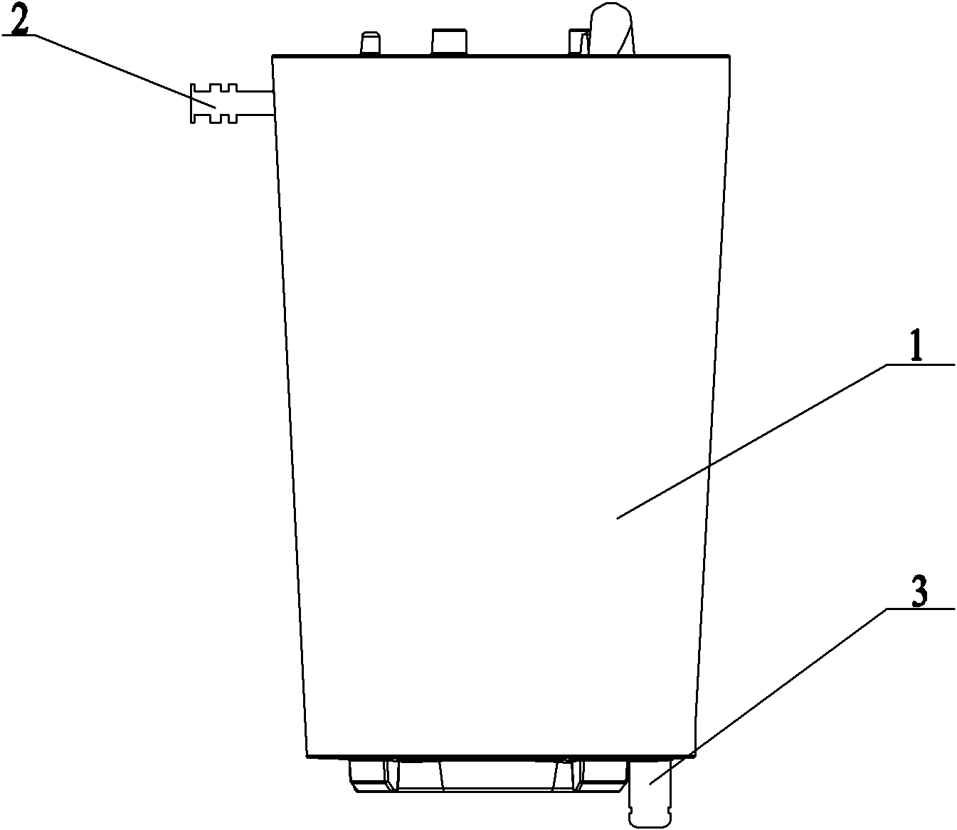
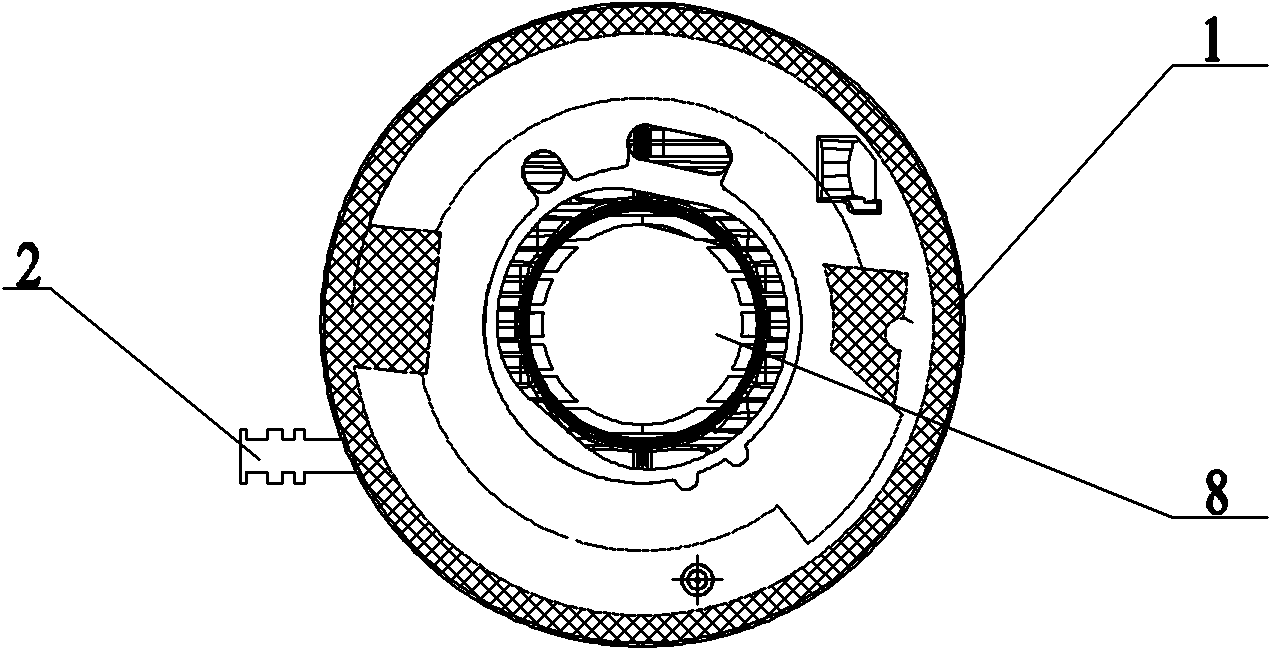
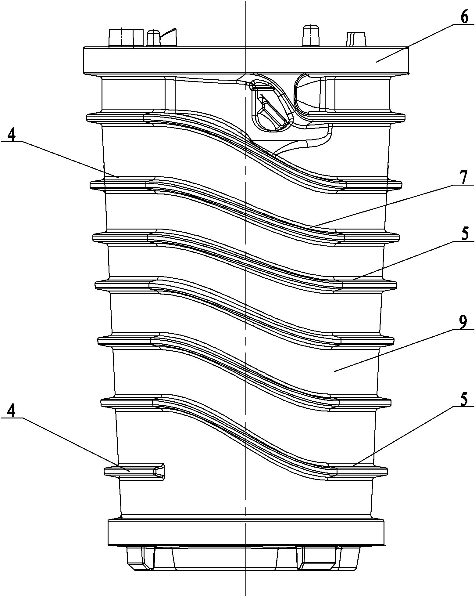
[0012] Such as Figure 1~Figure 3 Shown: the present invention comprises heat exchanger housing 1, water inlet pipe 2, water outlet pipe 3, first positioning block 4, second positioning block 5, combustion chamber 6, third positioning block 7, combustion chamber cavity 8 and transmission Heat medium channel 9.

[0013] Such as figure 1 , figure 2 and image 3 As shown: the heat exchanger housing 1 is provided with a combustion chamber 6 , and the combustion chamber 6 includes a combustion chamber cavity 8 . The outer wall of the combustion chamber 6 is provided with uniformly distributed first positioning blocks 4 and second positioning blocks 5 , and the first positioning blocks 4 and the second positioning blocks 5 are alternately distributed. The corresponding adjacent ends of the first positioning block 4 and the second positioning block 5 are connect...


PUM


Abstract

The invention relates to a heat exchanger structure, comprising a heat exchanger casing and a combustion chamber, wherein the peripheral face of the combustion chamber is provided with a plurality of positioning bosses which are fixed with an inner wall of the heat exchanger casing; and heat transfer medium passages are formed between adjacent positioning bosses and are spirally shaped along the axis of the combustion chamber. In the heat exchanger structure, the heat transfer medium passages are formed between adjacent positioning bosses and are spirally shaped along the axis of the combustion chamber; the positioning bosses are fixed in a sealing manner with the inner wall of the heat exchanger casing; heat energy inside a cavity of the combustion chamber can achieve direct heat exchange with heat transfer media, thus the efficiency of heat exchange is enhanced; the heat absorption area of the media is enlarged, the heat conversion efficiency is enhanced, the number of laminar flow layer decreases, the number of turbulent flow layer increases and the heat conversion coefficient is raised; and simultaneously, the particles inside the heat transfer medium passages are hardly deposited and scale-formed, the maintenance times is reduced, the service life is prolonged and the using cost is lowered.

Description

technical field [0001] The invention relates to a heat exchanger structure, in particular to a heat exchanger structure in which a heat exchanger shell has an outer spiral water flow path, and belongs to the technical field of heat exchangers. Background technique [0002] As heat transfer equipment, heat exchangers can be seen everywhere, and their applications are very popular, especially in areas with high energy consumption. With the rapid development of energy-saving technology, there are more and more types of heat exchangers, which are suitable for different media, different working conditions, Heat exchangers with different temperatures and pressures have different structures and types, and the development of heat exchangers is also developing towards high efficiency and energy saving. At present, the heat transfer efficiency of heat exchangers on the market is generally between 75% and 90%, and its heat transfer efficiency cannot meet the current needs of energy sav...

Claims


Application Information

Patent Timeline
Patent Type & Authority Applications(China)
IPC IPC(8): F24H1/43F24H9/18
Inventor 包建忠
Owner WUXI XIZHOU MACHINERY
Why Eureka
Try Eureka