Method and device for zero point calibration of gas pressure sensor

A gas pressure and zero point calibration technology, which is applied in the direction of measuring fluid pressure, measuring devices, instruments, etc., can solve the problems of heavy workload, complicated operation, and high cost, and achieve the effects of reducing workload, simple operation, and reducing calibration costs

Inactive Publication Date: 2010-02-24
LOCOMOTIVE & CAR RES INST OF CHINA ACAD OF RAILWAY SCI
View PDF0 Cites 29 Cited by
  • Summary
  • Abstract
  • Description
  • Claims
  • Application Information

AI Technical Summary

Problems solved by technology

[0007] The main purpose of the embodiments of the present invention is to provide a zero point calibration solution for gas pressure sensors to solve the above-mentioned problems of manual calibration to solve the problem of zero point drift, complex operation, heavy workload, and high cost

Method used


Image

  • Method and device for zero point calibration of gas pressure sensor
  • Method and device for zero point calibration of gas pressure sensor
  • Method and device for zero point calibration of gas pressure sensor

Examples


Embodiment 1

[0043] An embodiment of the present invention provides a zero point calibration method for a gas pressure sensor, Figure 4 is the flowchart of the method, such as Figure 4 As shown, the method includes:

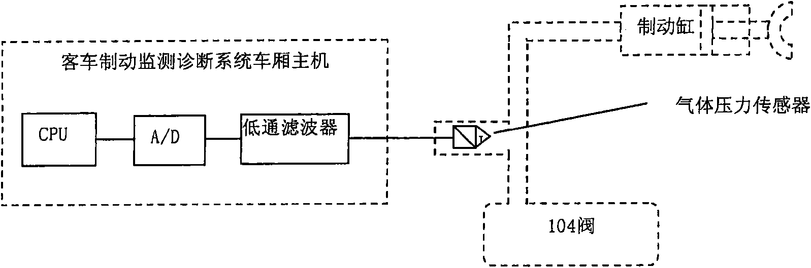
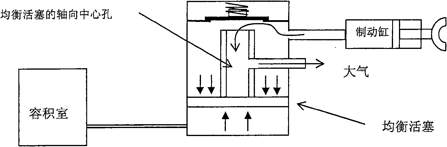
[0044] Step 401, when the brake cylinder is relieved, obtain the pressure value of the brake cylinder;

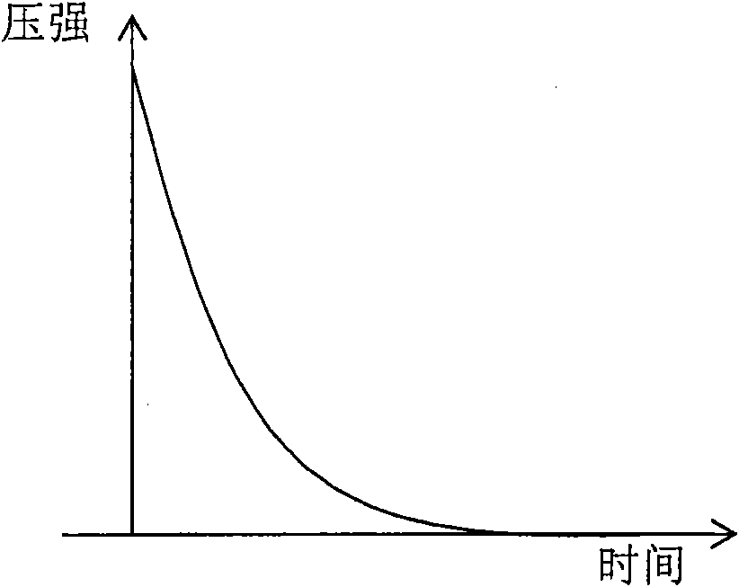
[0045] Step 402, according to the time when the pressure value is obtained and the pressure value, it is judged whether the relief process is normal;

[0046] Step 403, when the relief process is normal, it is judged whether the pressure value of the brake cylinder reaches zero;

[0047] Step 404, when the pressure value of the brake cylinder reaches zero, compare the currently obtained pressure value with the pre-stored comprehensive error nominal value;

[0048] Step 405, when the currently acquired pressure value is less than or equal to the nominal value of the integrated error, use the currently acquired pressure value as the zero point correction value;

[0049...

Embodiment 2

[0118] The embodiment of the present invention also provides a gas pressure sensor zero point calibration device, Figure 8 is the structural block diagram of the device, such as Figure 8 As shown, the device includes:

[0119] A pressure acquisition unit 1, configured to acquire the pressure value of the brake cylinder and the moment when the pressure value is acquired;

[0120] The first judgment unit 2 is connected to the pressure acquisition unit 1, and is used to judge whether the relief process is normal according to the time and pressure value of the pressure value acquired by the pressure acquisition unit 1;

[0121] The second judging unit 3 is connected to the first judging unit 2, and is used to judge whether the pressure value of the brake cylinder reaches zero when the relief process is normal;

[0122] The comparison unit 4 is connected to the pressure acquisition unit 1 and the second judgment unit 3, and is used to combine the pressure value currently acquir...


PUM


Abstract

The invention provides a method and a dehvice for the zero point calibration of a gas pressure sensor, which comprises the steps that: when a brake cylinder is released, the pressure value of the brake cylinder is obtained; the releasing process is judged to be normal or abnormal according to the time the pressure value is obtained and according to the pressure value; when the releasing process isnormal, the pressure value of the brake value is judged to whether reach zero or not; when the pressure value of the brake reaches zero, the pressure value obtained currently is compared with a pre-stored composite error nominal value; when the pressure value obtained currently is smaller than or equal to the composite error nominal value, the pressure value obtained currently is regarded as a zero point correct value; and the zero point of the gas pressure sensor is calibrated according to the zero point correct value. The method and the device can solve the problem of zero point drift and have simple operation and lowered workload and calibration cost.

Description

technical field [0001] The invention relates to the field of passenger car brake detection, in particular to a zero point calibration method and device for a gas pressure sensor. Background technique [0002] At present, the 104-type air brake (hereinafter referred to as the 104 brake) occupies a large proportion in the use of railway passenger car brakes, and is the main brake of the 25-type passenger car. During long-term use, the 104 brake will experience abnormal braking, such as poor relief. Abnormal braking has a great impact on the safety of train operation. For this reason, a passenger car brake monitoring and diagnosis system has been developed, which is used to monitor and diagnose the operating status of the railway passenger car braking system. figure 1 It is a simple schematic diagram of the passenger car brake monitoring and diagnosis system, such as figure 1 As shown, the passenger car brake monitoring and diagnosis system includes: passenger car brake detec...

Claims


Application Information

Patent Timeline
Patent Type & Authority Applications(China)
IPC IPC(8): G01L27/00
Inventor 王旭如陈朝发
Owner LOCOMOTIVE & CAR RES INST OF CHINA ACAD OF RAILWAY SCI
Why Eureka
Try Eureka