Distribution photometer

A goniophotometer and light source technology, applied in the field of luminous flux measurement of light sources and lamps, can solve the problems of adjusting light affecting depolarization effect, high cost, narrow spectral band, etc.

Active Publication Date: 2011-07-20
HANGZHOU EVERFINE PHOTO E INFO
View PDF0 Cites 0 Cited by
  • Summary
  • Abstract
  • Description
  • Claims
  • Application Information

AI Technical Summary

Problems solved by technology

[0013] The use of low polarization-dependent mirrors is the only way to reduce polarization errors in rotating mirror goniophotometers. Generally, low-polarization-dependent mirrors are depolarized by surface coating, but this method is costly on the one hand, and on the other On the one hand, this method can only reduce the polarization problem caused by the above-mentioned specular reflection to a certain extent, and the reflectivity difference between the p-wave and s-wave of the mirror still exists. The incident angle is limited, and adjusting the incident angle of the light will seriously affect the depolarization effect

Method used


Image

  • Distribution photometer
  • Distribution photometer
  • Distribution photometer

Examples


Embodiment 1

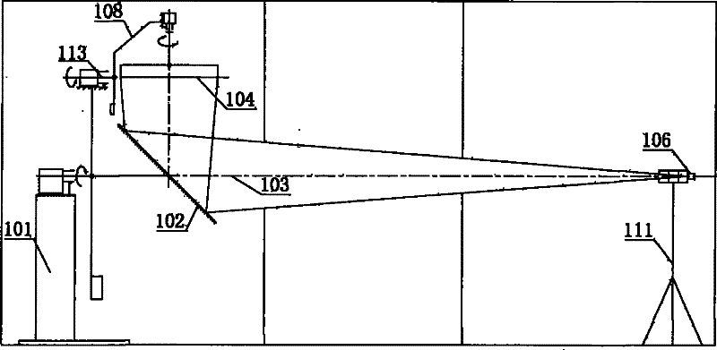
[0059] like Figure 7 A schematic diagram of an embodiment of the shown goniophotometer of the present invention includes two bases 1, 11 and a horizontal main axis 3, the first base 1 is provided with a first main shaft rotation drive mechanism 7, and the first main shaft rotation drives The output shaft of the mechanism 7 is coaxial with the horizontal main axis 3 of the goniophotometer, and the output shaft is connected with the polarizing mirror 2 and the first rotating arm 5 . The main axis 3 passes through the center of the polarizing mirror 2 , and the first main shaft rotation drive mechanism 7 drives the polarizing mirror 2 and the first rotating arm 5 to rotate around the main axis 3 during measurement. The light source 4 to be tested is clamped on the lamp arm 8, and one end of the lamp arm 8 is connected with one end of the first rotating arm 5 through the synchronous driving mechanism of the auxiliary shaft 13. During the measurement, the first rotating arm 5 driv...

Embodiment 2

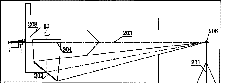
[0061] like Figure 8 Shown is a schematic diagram of a second embodiment of the goniophotometer of the present invention, comprising two bases 1 , 11 and a horizontal main axis 3 . The first base 1 is provided with a first spindle rotation drive mechanism 7, the output shaft of the first spindle rotation drive mechanism 7 is coaxial with the main axis 3, and the first arm 5 is connected to the first spindle rotation drive mechanism 7 through the first spindle rotation drive mechanism 7. On a base 1, it can rotate around the main axis 3. The polarizing mirror 2 and the second detector 16 are installed at both ends of the rotating arm. The light source under test 4 is connected to the first base 1 through the lamp arm 8, and is located on the main axis 3. A vertical axis rotation drive mechanism is installed between the light source under test 4 and the lamp arm, but the light source under test 4 rotates around its own vertical axis. , to switch between different measurement ...

Embodiment 3

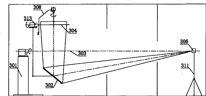
[0063] like Figure 9 A schematic diagram of an embodiment of the shown goniophotometer of the present invention includes two bases 1, 11 and a horizontal main axis 3, the first base 1 is provided with a first main shaft rotation drive mechanism 7, and the first main shaft rotation drives The output shaft of the mechanism 7 is coaxial with the horizontal main axis 3 of the goniophotometer, and the output shaft is connected with the first rotating arm 5 , and the first rotating arm 5 is driven by the first rotating arm 5 to rotate around the main axis 3 during measurement. The light source 4 to be tested is clamped on the lamp arm 8, and one end of the lamp arm 8 is connected with one end of the first rotating arm 5 through a synchronous driving mechanism of the auxiliary shaft 13. During the measurement, the first rotating arm 5 drives the lamp arm 8 around the main axis 3 At the same time, the lamp arm 8 rotates synchronously and reversely around the auxiliary shaft 13 to mai...


PUM


Abstract

The invention discloses a distribution photometer. The distribution photometer is characterized in that: light emitted by a measured light source in a direction emitted is reflected by a first polarizing reflector in circular motion relative to the measured light source and then is reflected onto a detector by other subsequent reflectors; all reflectors in a light path establish and maintain a depolarization reflector group relation all the time during measurement; and because polarization generated by the polarizing reflector and the polarization generated by a compensation reflector inside the reflector group compensates and counteracts mutually, the intensity of reflected light entering the detector finally is also independent of the polarizing state of incident light and the reflectorgroup in the light path does not bring additional polarization to the reflected light. The distribution photometer can conveniently and effectively eliminate polarization problems caused by specular reflection and reduce or eliminate measurement errors caused by reflector polarization, thereby increasing measurement precision.

Description

【Technical field】 [0001] The invention relates to a measuring instrument for light and radiation, which is mainly used for light intensity distribution (or light distribution performance) in various directions of various light sources and lamps such as indoor lamps, road lamps, spotlight lamps, automobile lamps, etc. measurement, and luminous flux measurement of light sources and luminaires. 【Background technique】 [0002] Goniophotometers generally use illuminance measurement and the inverse square law of illuminance distance to measure the light intensity distribution of light sources or lamps. In order to satisfy the inverse square law of illuminance distance, the optical path distance between the detector and the light source under test must be long enough to make the detection The light source under test can be regarded as a point light source approximately. At the same time, in order to achieve accurate measurement, the goniophotometer must keep the light source under...

Claims


Application Information

Patent Timeline
Patent Type & Authority Patents(China)
IPC IPC(8): G01M11/02G01J1/04G01J1/00
Inventor 潘建根
Owner HANGZHOU EVERFINE PHOTO E INFO
Why Eureka
Try Eureka