Magnetic core of rectangular flat transformer
A flat-panel transformer, rectangular technology, applied in the direction of transformer/inductor core, inductance/transformer/magnet manufacturing, electrical components, etc., can solve the problems of close distance between winding leads, inconvenient wiring, obvious lead interference, etc. Achieving the effect of avoiding cracking, convenient lead and small loss
Inactive Publication Date: 2010-02-24
CHENGDU JINZHICHUAN ELECTRONICS
View PDF0 Cites 1 Cited by
- Summary
- Abstract
- Description
- Claims
- Application Information
AI Technical Summary
Problems solved by technology
[0002] At present, small flat-panel transformers use circular magnetic cores. Due to the small openings, the lead wires of the windings are relatively close to each other, and the interference between the lead wires is obvious, and it is inconvenient to wire when assembling electronic products.
Method used
View moreImage
Smart ImageViewing Examples

Examples
Embodiment Construction
[0011] The present invention will be further described below in conjunction with the accompanying drawings and embodiments.
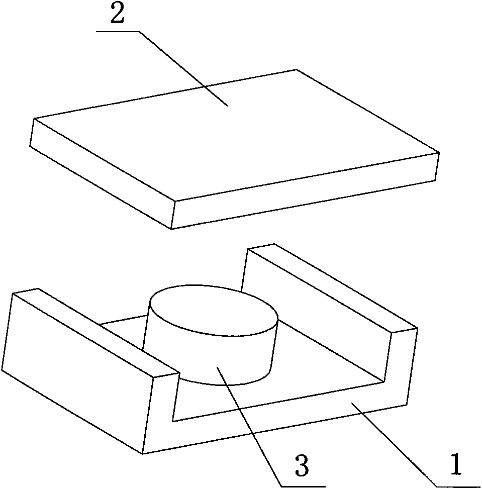
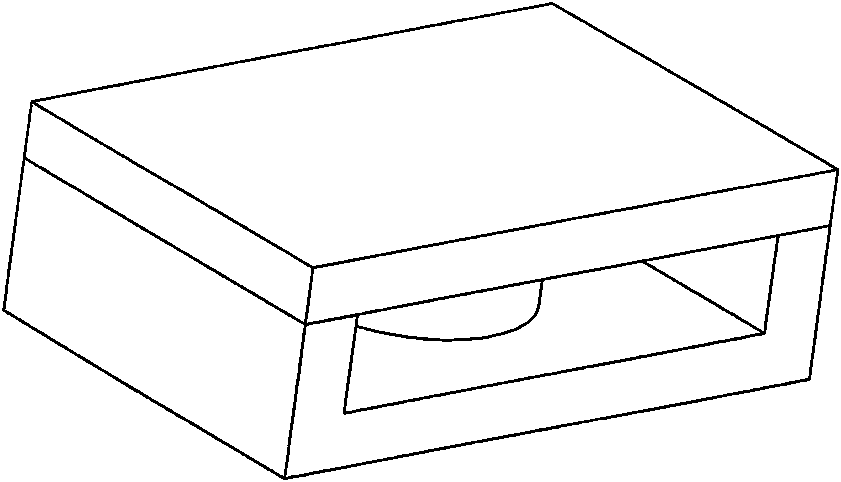
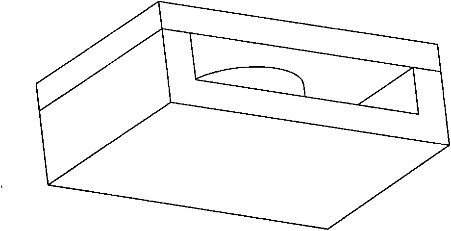
[0012] The rectangular plate transformer magnetic core includes a groove-shaped main body 1 and a cover plate 2. The center of the main body 1 is a cylindrical winding post 3. The shape of the main body 1 is rectangular, and the cover plate 2 cooperates with the main body.
[0013] The main body 1 and the cover plate 2 are connected by glue. Since the main body 1 is rectangular and has a large opening, the lead wires of the windings can be far apart, reducing mutual interference and making wiring more convenient. Such as Figure 1-5 .
Login to View More PUM
 Abstract
The invention discloses a magnetic core of a rectangular flat transformer, which belongs to the technical field of electronic components. The magnetic core of the rectangular flat transformer comprises a groove-shaped main body and a cover plate, wherein the center of the main body is provided with a cylindrical winding column, the appearance of the main body is rectangular, and the cover plate ismatched with the main body. The invention has small interference among leading wires, little resistance and loss and convenient wire leading. The invention is suitable for manufacturing minitype flattransformers.
Description
Technical field [0001] The invention relates to a transformer magnetic core, in particular to a flat transformer magnetic core, which belongs to the technical field of electronic devices. Background technique [0002] At present, small planar transformers use circular magnetic cores. Due to the small openings, the lead wires of the windings are relatively close to each other, the interference between the lead wires is obvious, and it is inconvenient to wire when assembling electronic products. Contents of the invention [0003] In order to overcome the above-mentioned shortcomings of the existing flat transformer magnetic core, the present invention provides a small flat transformer magnetic core with large openings. [0004] The technical solution adopted by the present invention to solve the technical problem is: a rectangular plate transformer magnetic core, including a groove-shaped main body and a cover plate, the center of the main body is a cylindrical winding post,...
Claims
Login to View More Application Information
Patent Timeline
 Patent Type & Authority Applications(China)
IPC IPC(8): H01F27/24H01F41/02
Inventor 周新龙周洪江
Owner CHENGDU JINZHICHUAN ELECTRONICS