
Indicating method and base station, decoding method and terminal for wireless channel resource allocation

A resource allocation and wireless channel technology, applied in wireless communication, transmission path separation device, digital transmission system, etc., can solve the problems of not giving indication methods and decoding methods, etc.

Active Publication Date: 2010-02-24
ZTE CORP
View PDF2 Cites 65 Cited by
  • Summary
  • Abstract
  • Description
  • Claims
  • Application Information

AI Technical Summary

Problems solved by technology

[0038] 1) Only the total number of states is given, but the indication method and decoding method corresponding to each state (each possible resource allocation position) is not given;
[0039] 2) If the number of clusters is m, it is necessary to add m virtual RBGs, and there is a certain number of redundant states

Method used


Image

  • Indicating method and base station, decoding method and terminal for wireless channel resource allocation
  • Indicating method and base station, decoding method and terminal for wireless channel resource allocation
  • Indicating method and base station, decoding method and terminal for wireless channel resource allocation

Examples


Embodiment 1

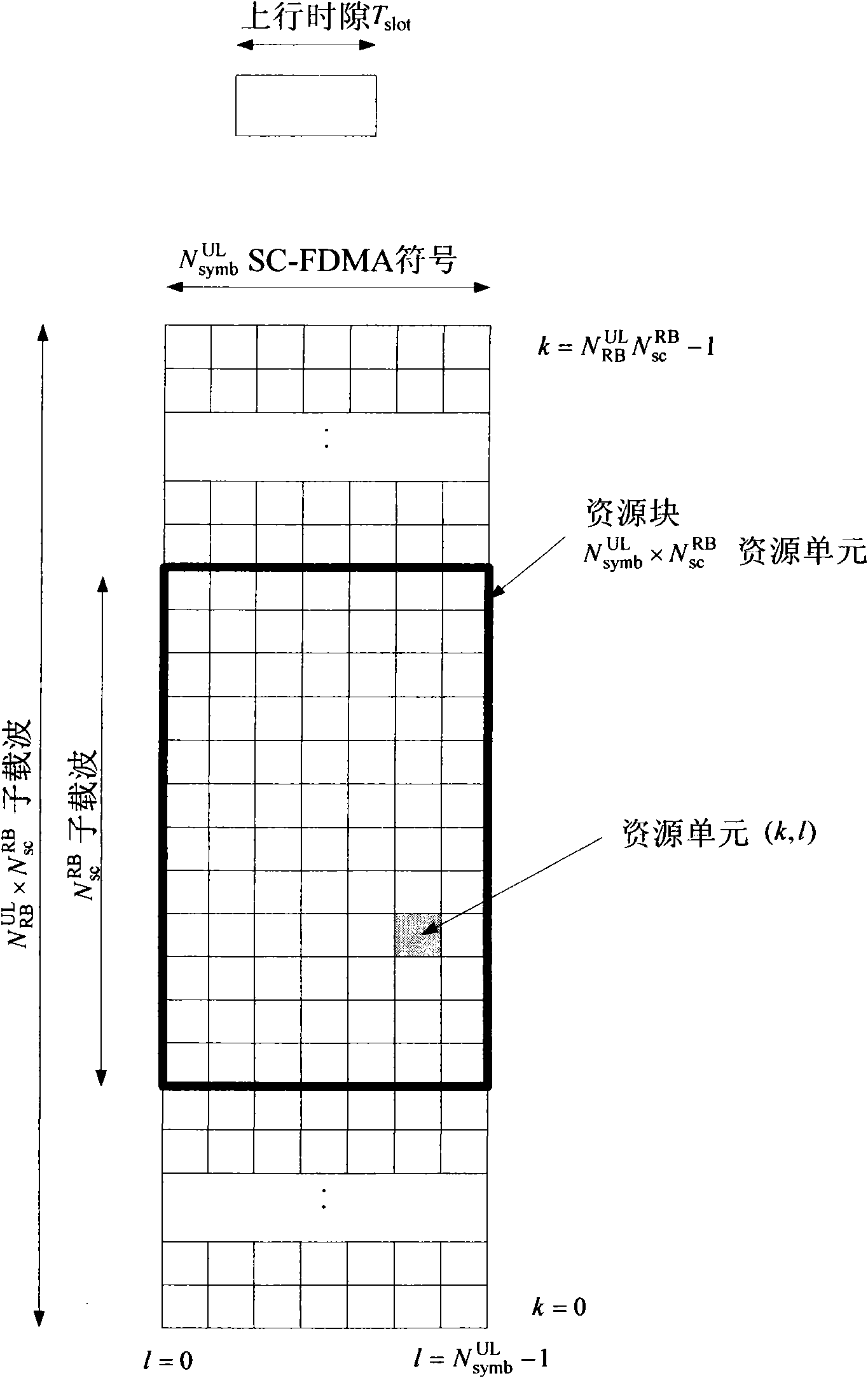
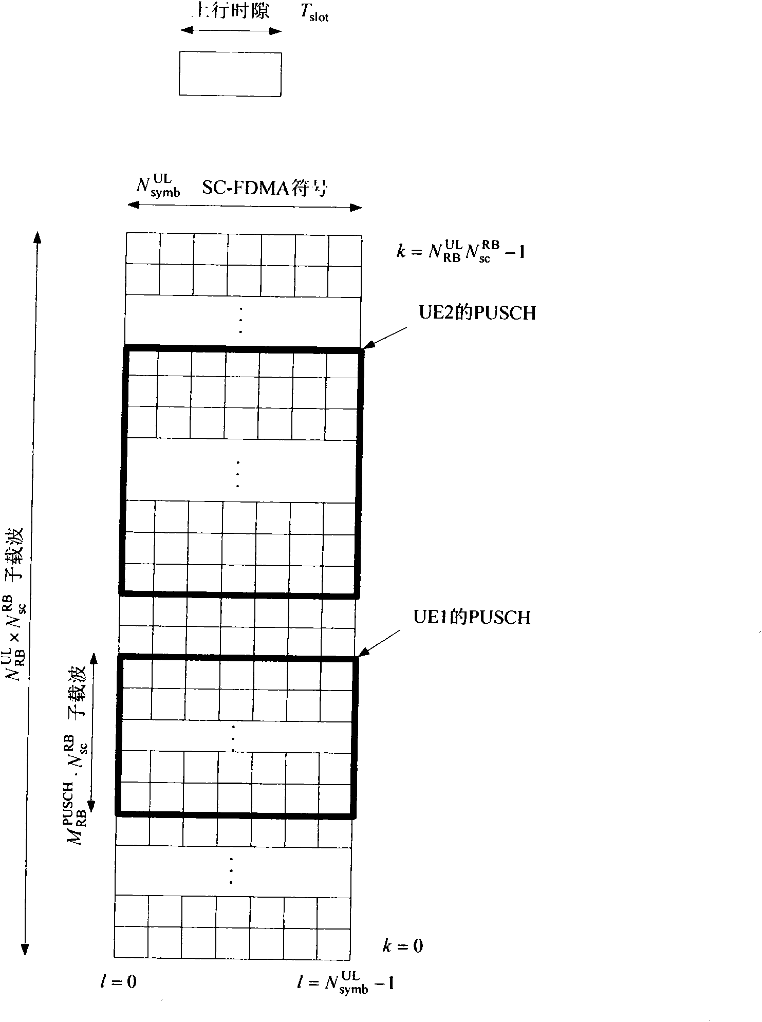
[0189] Assume that in the LTE-A system, the system bandwidth of a component carrier is 20MHz, and the corresponding number of PRBs is N RB UL = 100 ; In this component carrier, the number of PRBs corresponding to the bandwidth range used for PUSCH discontinuous resource allocation is N RB PUSCH = N RB UL = 100 ; The size of the resource block group is P=4, and the number of RBGs corresponding to the system bandwidth of the component carrier (that is, the bandwidth used for PUSCH discontinuous resource allocation) is

[0190]

[0191] and, because

[0192] N RB UL mod P = 100 mod 4 = 0

[0193] The size of...

Embodiment 2

[0197]Assume that in the LTE-A system, the system bandwidth of a component carrier is 15MHz, and the corresponding number of PRBs is N RB UL = 75 , In this component carrier, the number of PRBs corresponding to the bandwidth range used for PUSCH discontinuous resource allocation is N RB PUSCH = N RB UL = 75 ; The size of the resource block group is P=4, and the number of RBGs corresponding to the system bandwidth of the component carrier (that is, the bandwidth used for PUSCH discontinuous resource allocation) is

[0198]

[0199] and, because

[0200] N RB UL mod P = 75 mod 4 = 3 > 0 ...

Embodiment 3

[0206] Assume that in the LTE-A system, the system bandwidth of a component carrier is 10MHz, and the corresponding number of PRBs is N RB UL = 50 ; In this component carrier, the number of PRBs corresponding to the bandwidth range used for PUSCH discontinuous resource allocation is N RB PUSCH = N RB UL = 50 ; The size of the resource block group is P=3, and the number of RBGs corresponding to the system bandwidth of the component carrier (that is, the bandwidth used for PUSCH discontinuous resource allocation) is

[0207]

[0208] and, because

[0209] N RB UL mod P = 50 mod 3 = 2 > 0 ...


PUM


Abstract

The present invention provides a method for indicating wireless channel resource allocation, indicating a starting position and an ending position of m group(s) distributed to a terminal, and indicating a first RBG and a last RBG for a group containing at least two RBGs; when the group contains one RBG and is not the last one, indicating the RBG contained by the group and a previous RBG of a firstRBG contained by a next group; when the group only contain one RBG and is the last one, indicating the RBG and a virtual RBG; or when the group only contain one RBG and is not the first one, indicating a following RBG of the last RBG contained by a previous group, and the RBG contained by the group; when the group only contain one RBG and is the first one, indicating a virtual RBG and the RBG contained by the group. The invention also provides a corresponding decoding method, a base station and a terminal for the wireless channel resource allocation. According to the invention, no matter whatis a number m of the groups, it is nothing remains but to add one virtual RBG only, such that signalling spending is minimum.

Description

technical field [0001] The present invention relates to the field of mobile communication, in particular to a method for indicating wireless channel resource allocation, a base station, a decoding method and a terminal. Background technique [0002] The LTE (Long Term Evolution, Long Term Evolution) system adopts a centralized scheduling method of the base station to control the transmission of the Physical Uplink Shared Channel (Physical Uplink Shared Channel, PUSCH) of the user terminal (User Equipment, UE). [0003] In the LTE system, the PUSCHs of multiple user terminals in a cell are frequency-division multiplexed to the uplink system bandwidth, that is, the PUSCHs of different UEs are orthogonal in the frequency domain. The base station indicates the radio channel resources allocated for the PUSCH of a certain UE through an uplink scheduling grant signaling (Uplink Scheduling Grant, UL grant for short). [0004] Uplink channel resource allocation in the LTE system tak...

Claims


Application Information

Patent Timeline
IPC IPC(8): H04W72/04H04W72/14
CPCH04L5/0091H04L5/0007H04W72/042H04W72/23
Inventor 朱鹏郝鹏喻斌张禹强王瑜新张戎
Owner ZTE CORP
Learn More