
Yarn winder

A yarn winding machine, yarn technology, applied in the direction of thin material handling, delivery of filamentous materials, transportation and packaging, etc., can solve the problems of reducing manufacturing costs

Active Publication Date: 2010-03-03
TMT MACHINERY INC
View PDF2 Cites 8 Cited by
  • Summary
  • Abstract
  • Description
  • Claims
  • Application Information

AI Technical Summary

Problems solved by technology

Therefore, the existing structure with the turntable mechanism is difficult to effectively reduce the manufacturing cost

Method used


Image

  • Yarn winder
  • Yarn winder
  • Yarn winder

Examples


Embodiment Construction

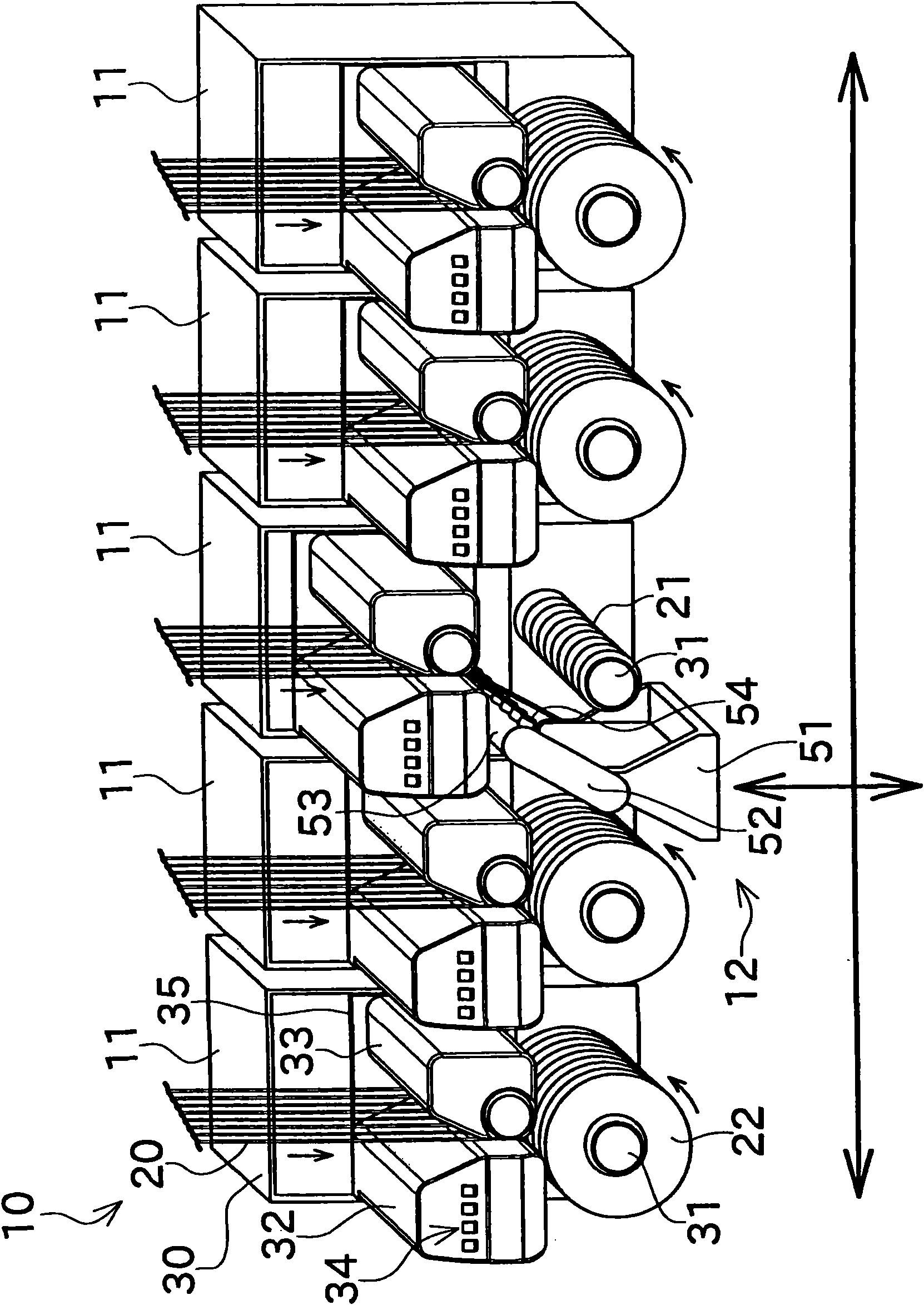
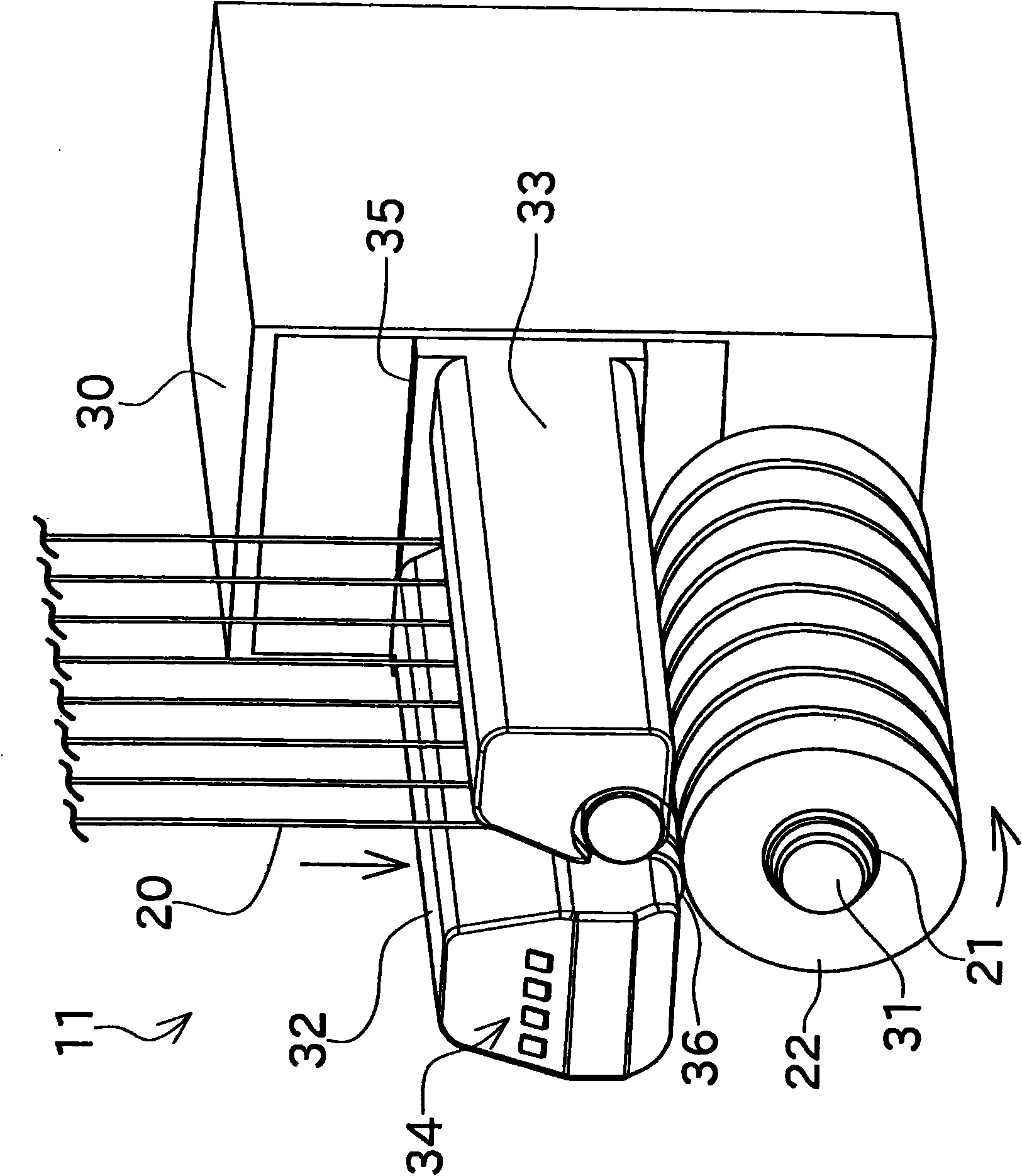
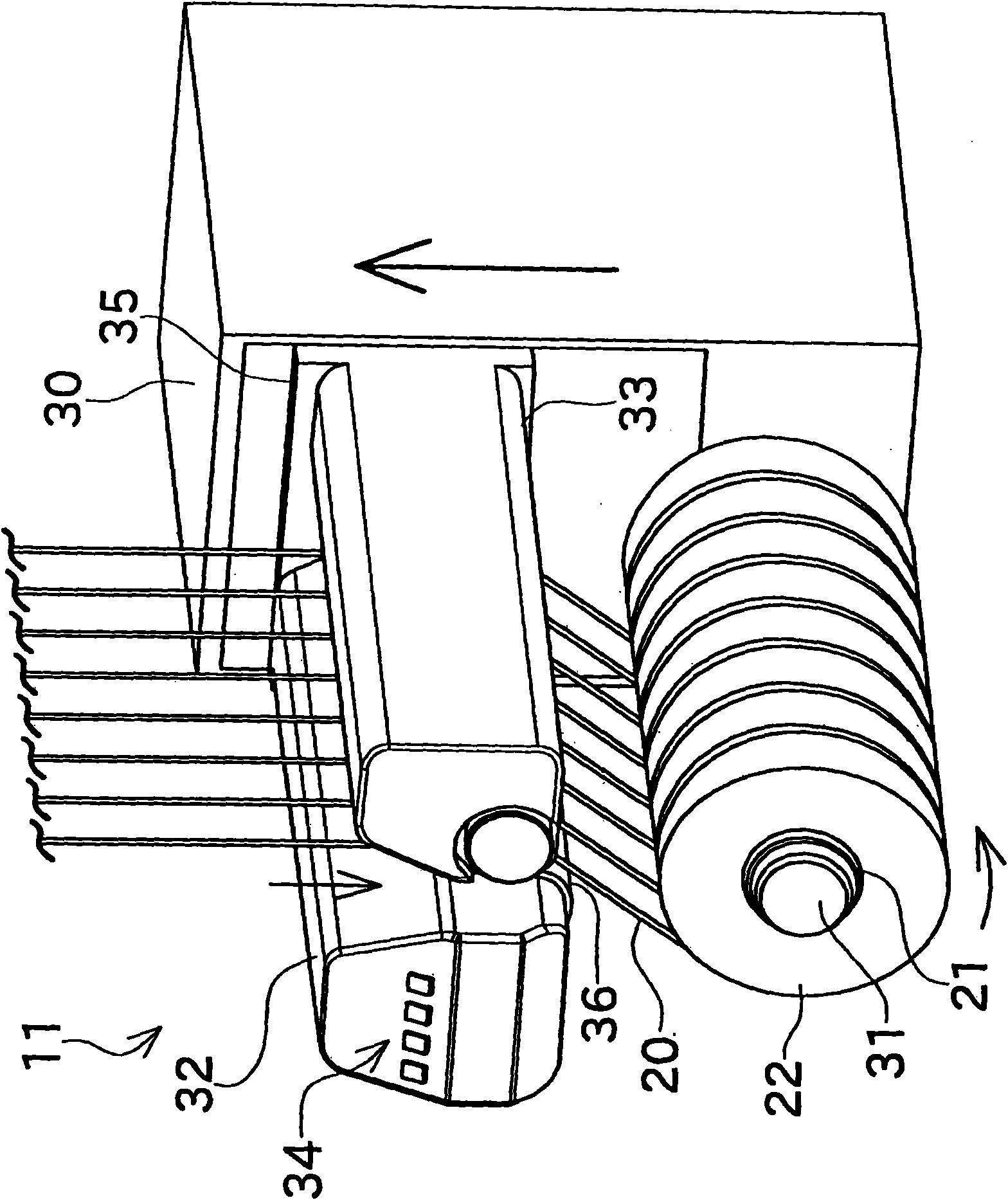
[0027] Preferred embodiments of the present invention will be described below with reference to the drawings. figure 1 It is a perspective view showing the appearance of a winder according to an embodiment of the present invention. figure 2 It is a perspective view showing the state of the winding unit during the winding operation.

[0028] Such as figure 1 As shown, the winder (yarn winding machine) 10 of this embodiment has a plurality of winding units 11, a switching device 12, and a control unit not shown. The winding unit 11 is a unit for winding an elastic yarn 20 such as spandex fiber around a winding tube 21 to form a package 22 having a predetermined length. In this embodiment, a polyurethane yarn is used as the elastic yarn 20 . The switching device 12 is a device for replacing the winding tube 21 without stopping the supply of the elastic yarn 20 from the upstream when the package 22 becomes a fully wound state (predetermined length). Structure. The control un...


PUM


Abstract

The invention provides a yarn winder capable of compacting the device structure and reducing the cost of manufacture by simplifying the structure for replacing a coiling tube. A winding machine has a coiling unit (11) and a switching mechanism (12), the coiling unit (11) has a coiling shaft (31) for driving the coiling tube (21) to rotate, the switching mechanism (12) has a plurality of nozzles (54) for sucking and capturing the yarn conveyed from the upstream of the coiling shaft (31) based on each yarn. The coiling tube (21) is changed in the way that the nozzle (54) sucks and captures the yarn reeled at one side of the upstream at the prescribed length, in the case, the package is drawn out from the coiling shaft (31), and the empty coiling tube (21) is mounted on the coiling shaft (31).

Description

technical field [0001] The present invention relates to a structure for replacing a take-up tube of a yarn take-up machine. Background technique [0002] In a yarn winding machine that winds a yarn onto a take-up tube to form a package of a predetermined length, a structure in which the take-up tube is replaced by a turntable mechanism is known. Patent Document 1 and Patent Document 2 disclose such a yarn winding machine. Both Patent Document 1 and Patent Document 2 disclose yarn winding with two bobbin holders for mounting winding tubes and a turntable for switching the two bobbin holders to the winding position and the standby position. machine. When changing the winding tube, the position of the two bobbin holders is changed by rotating the turntable plate, and the yarn is delivered. Thus, the winding tube can be replaced without stopping the supply of the yarn sent from the upstream side of the yarn winding machine. [0003] [Patent Document 1] Japanese Patent No. 31...

Claims


Application Information

Patent Timeline
IPC IPC(8): B65H54/02B65H67/04B65H67/08
CPCB65H67/0405B65H2701/319B65H54/34B65H67/048
Inventor 桥本欣三
Owner TMT MACHINERY INC
Features
  • Generate Ideas
  • Intellectual Property
  • Life Sciences
  • Materials
  • Tech Scout
  • Unparalleled Data Quality
  • Higher Quality Content
  • 60% Fewer Hallucinations
Learn More