Straight-through type solar energy vacuum heat collecting tube

A vacuum heat collecting tube and solar energy technology, which is applied in the field of heat collecting tubes, can solve the problems of poor feasibility, can not achieve explosion-proof tubes, explosion tubes, etc., and achieve the effects of good economic and social benefits, simple structure design, and reasonable structure design.

Active Publication Date: 2010-03-03
HAINING BAOGUANG SOLAR ENERGY INDAL
View PDF0 Cites 4 Cited by
  • Summary
  • Abstract
  • Description
  • Claims
  • Application Information

AI Technical Summary

Problems solved by technology

Although the bellows is made of glass, due to its unreasonable structural design, the bellows has no elasticity, cannot be stretched and stretched, and cannot play the role of an explosion-proof tube; at the same time, the bellows cannot be made in practice; In addition, the heat collecting tube includes metal tubes and glass tubes, the structure and process design are complicated, impractical and poor in feasibility
[0006] In addition, there are other inventions and utility model patent applications for vacuum heat collecting tubes, but their structural design is even more unreasonable
At the same time, the above structures cannot be simply combined, otherwise it will be more likely to cause the tube to explode, or cause poor heat collection effect, or cause high cost, or make it impossible to implement

Method used


Image

  • Straight-through type solar energy vacuum heat collecting tube
  • Straight-through type solar energy vacuum heat collecting tube
  • Straight-through type solar energy vacuum heat collecting tube

Examples


Embodiment 1

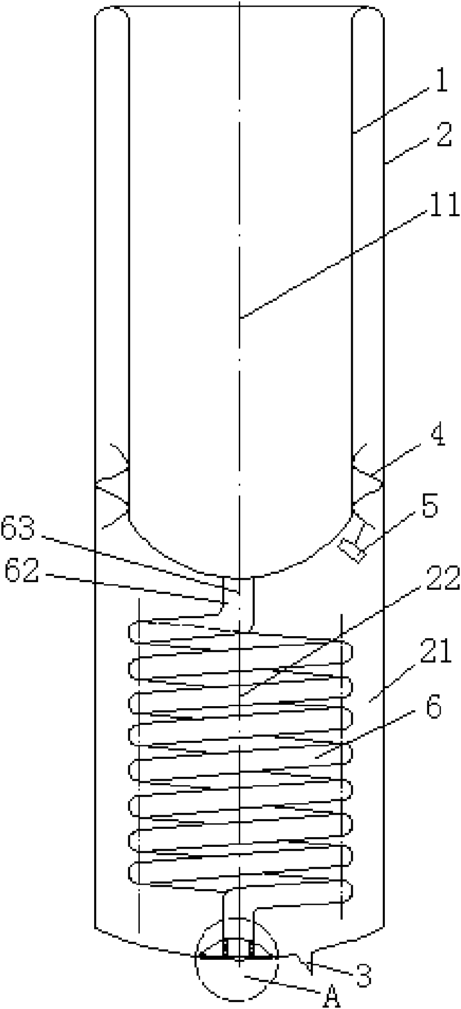
[0029] see Figure 1-Figure 3 , This embodiment is mainly composed of glass inner tube 1, glass outer tube 2, exhaust exhaust tail end 3, metal clip 4, air getter 5 and elastic glass coil 6.

[0030] The glass inner tube 1 and the glass outer tube 2 of the present invention are both hollow tubes, the glass inner tube 1 is located in the glass outer tube 2, and the inner and outer tube centerlines 11, 22 of the glass inner tube 1 and the glass outer tube 2 Coincident; the glass inner and outer tubes 1 and 2 are both evacuated; the exhaust tail end 3 is set on the glass outer tube 2, the air getter 5 is connected with the metal clip 4, and the metal clip 4 is located between the glass inner tube 1 and the glass outer tube. Between the tubes 2 and close to the lower part of the glass inner tube 1. Wherein: the metal clip 4 is used to prevent the eccentricity of the glass inner tube 1; the gas getter 5 is used to eliminate the residual gas in the vacuum tube, improve the vacuum d...

Embodiment 2

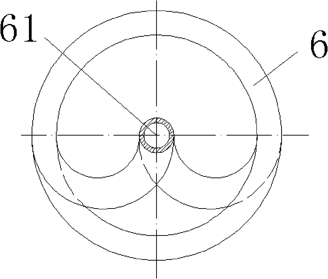
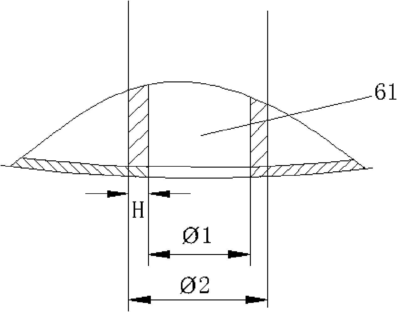
[0041] see Figure 4 Figure 5 , The present embodiment is also mainly composed of a glass inner tube 1, a glass outer tube 2, an exhaust exhaust tail end 3, a metal clip 4, an air getter 5 and an elastic glass coil 6.

[0042] Both ends of the flexible glass coil 6 are straight tubes 62, 65, and the direction of the axis is also the same as the axis of the glass outer tube 2, that is, the direction of the center line 22 of the outer tube; but in this embodiment, the straight The axes 621, 651 of the tubes 62, 65 do not coincide with the axis of the outer glass tube 2, that is, the centerline 22 of the outer tube, but are located on the side of the centerline 22 of the outer tube of the glass outer tube 2, and are aligned with the outer tube centerline 22 of the outer glass tube 2. The centerlines 22 are parallel.

[0043] Of course, the axes of the straight tubes 62 and 65 at both ends of the flexible glass coil 6 may not be on the same axis, but must be in the same directi...


PUM


Abstract

The invention relates to a straight-through type solar energy vacuum heat collecting tube, which is mainly applicable to families, office buildings and factories. The difference between the prior artand the invention is as follows: the upper end of the outer glass tube is welded with the upper end of an inner glass tube in the invention, wherein the inner glass tube is shorter than the outer glass tube in the axial direction, and thus a cavity is formed; the invention is also provided with an elastic glass coil tube made from the same materials as the inner glass tube and the outer glass tube, the elastic glass coil tube is arranged in the cavity, and the elastic glass coil tube is hollow; the elastic glass coil tube is provided with straight tubes at two ends, and the axial direction ofthe elastic glass coil tube is the same as that of the outer glass tube; one end of the elastic glass coil tube is welded with the outer end of the axial direction of the inner glass tube and communicated with the inner glass tube; and the other end of the elastic glass coil tube is welded with the inner end of the axial direction of the outer glass tube. The invention has reasonable, simple and practical design, not only can regulate the tension of the inner tube during expansion, but also can conduct in a bidirectional way, leads the inner sides of the tubes have no dirty, improves water quality and has high heat exchange rate.

Description

technical field [0001] The invention relates to a heat collecting tube, in particular to a straight-through solar vacuum heat collecting tube, which is mainly suitable for families, office buildings, factory buildings and corresponding places. Background technique [0002] Most of the solar vacuum heat collection tubes in the prior art are unidirectional, that is, the upper end of the outer tube is sealed with the upper end of the inner tube, the lower ends of the inner tube and the outer tube are sealed, and the cavity formed between the inner tube and the outer tube is sealed. Evacuate to create a vacuum. Because the water accumulated in the inner pipe cannot be discharged during use, long-term use will cause water deterioration, a large amount of pollutants will be accumulated in the pipe, the water quality is very poor, and the use is unhygienic. In order to change the water quality, some people have designed heat collecting tubes that are directly connected inside and ...

Claims


Application Information

Patent Timeline
Patent Type & Authority Applications(China)
IPC IPC(8): F24J2/46
CPCY02E10/40Y02B10/22Y02B10/20Y02P80/20
Inventor 王来雨
Owner HAINING BAOGUANG SOLAR ENERGY INDAL
Why Eureka
Try Eureka