Three-dimensional electromagnetic probe and gyromagnetic detection method

A three-dimensional electromagnetic and magnetic detection technology, applied in the direction of material magnetic variables, etc., can solve the problem of not having gyromagnetic characteristics, and achieve the effect of broad market prospects

Inactive Publication Date: 2010-03-03
帅立国
View PDF0 Cites 5 Cited by
  • Summary
  • Abstract
  • Description
  • Claims
  • Application Information

AI Technical Summary

Problems solved by technology

[0007] Technical problem: the purpose of the present invention is to solve the problems that the existing optical method-based metal material material uniformity detection instrument is destructive, the metal material electromagnetic non-destructive sorting and detection instrument is single-direction detection, and does not have gyromagnetic characteristics, etc., to provide A three-dimensional electromagnetic detection probe and a gyromagnetic detection method based on the three-dimensional probe. The three-dimensional electromagnetic probe and the gyromagnetic detection method combine the advantages of the existing optical method two-dimensional scanning and the electromagnetic detection method has no damage and has no requirements on the surface of parts. High advantages, can be effectively applied to the detection and evaluation of material uniformity of metal materials, and detect and warn of organizational abnormalities such as cracks through the unevenness of material distribution

Method used


Image

  • Three-dimensional electromagnetic probe and gyromagnetic detection method
  • Three-dimensional electromagnetic probe and gyromagnetic detection method
  • Three-dimensional electromagnetic probe and gyromagnetic detection method

Examples


Embodiment Construction

[0020] The technical solution of the present invention will be further described below in conjunction with the accompanying drawings and embodiments.

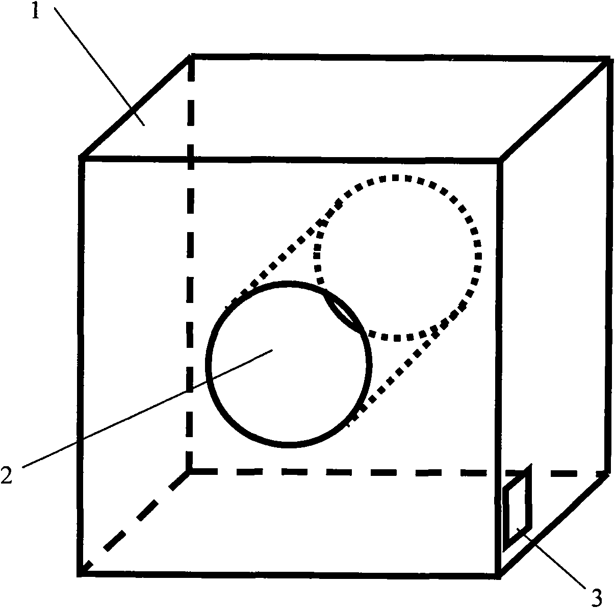
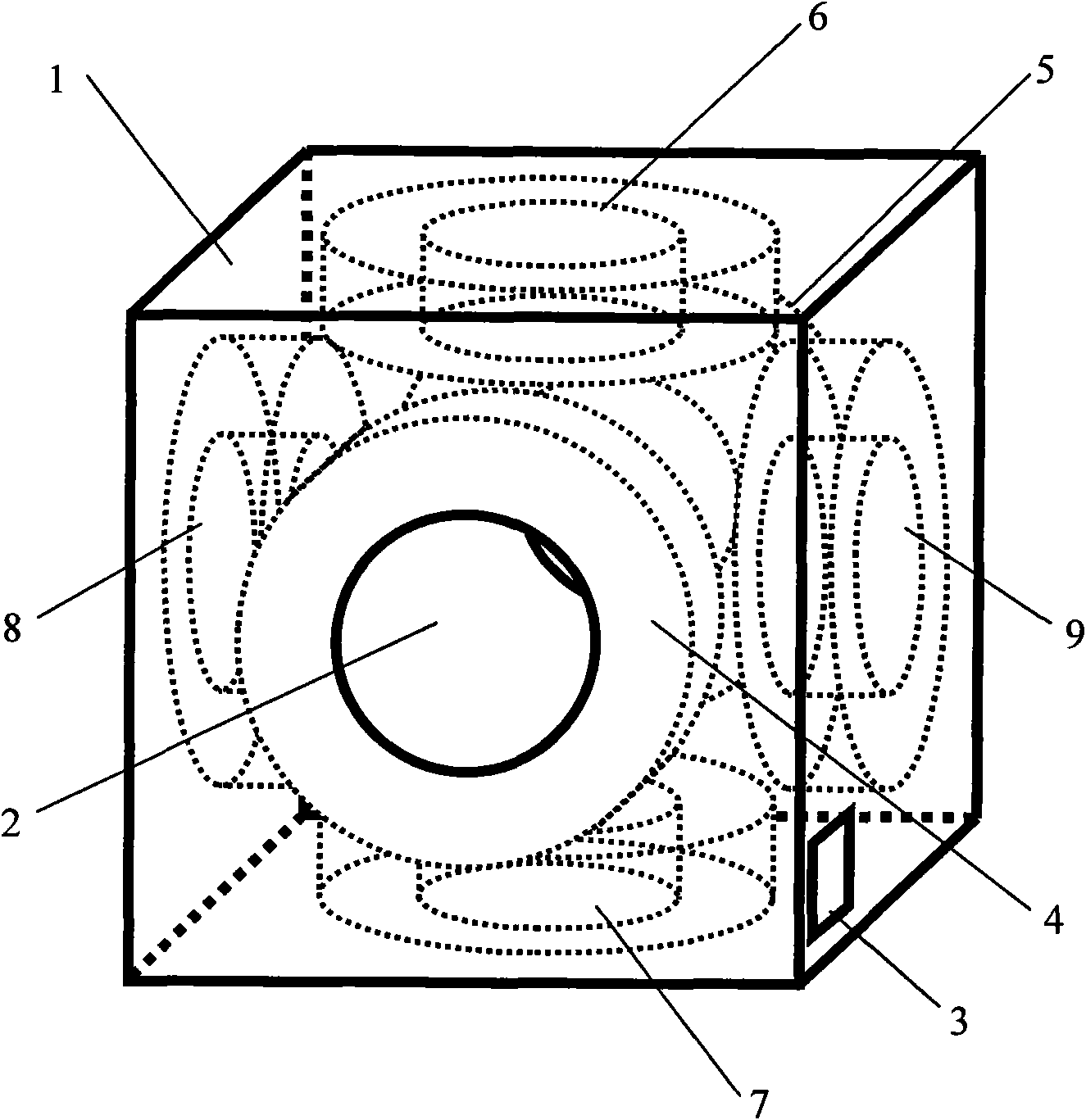
[0021] figure 1 It is a schematic diagram of the appearance of the three-dimensional gyromagnetic probe of the present invention. Among them, there are a probe body 1 , a detection hole 2 and a connection port 3 . figure 2 It is a structural schematic diagram of the three-dimensional gyromagnetic probe of the present invention. Among them, there are probe body 1 , detection hole 2 , wiring port 3 , front detection coil 4 , rear detection coil 5 , upper detection coil 6 , lower detection coil 7 , left detection coil 8 , and right detection coil 9 . Wherein, the detection hole 2 is located at the center of the probe body 1, the detection hole 2 can be a through hole, or a blind hole with one end closed, the wiring port 3 is located on the side of the probe body 1, the front detection coil 4 and the rear detection coil 5 Const...


PUM


Abstract

The invention relates to a three-dimensional electromagnetic probe and gromagnetic detection method for metal material nondestructive detection and evaluation. The electromagnetic probe comprises a probe body 1, a probe hole 2, a connection port 3, a front detection coil 4, a rear detection coil 5, an upper detection coil 6, a lower detection coil 7, a left detection coil 8 and a right detection coil 9. The probe is characterized in that each detection coil comprises a pair of magnet exciting coils and a pair of detection coils, exciting current of each coil is reasonably adjusted, thus providing a constant spatial rotating magnetic field for gyromagnetic detection. The result obtained by gromagnetic can generate an analog similar to the detected work piece by three-dimensional data visualization, abnormal material quality can be shown by obvious evagination or sinking on the analog, material quality uniformity and abnormal tissue in the interior of metal material can be obviously reflected, thus being helpful for detection personnel to rapidly evaluate the quality of the detected work piece. The invention not only can be used for detection and evaluation of ingredient, mechanic performance and tissue uniformity but also can detect and early warn of tissue abnormality such as crack by non-uniformity of material quality distribution.

Description

technical field [0001] The invention relates to a three-dimensional electromagnetic probe for non-destructive testing and evaluation of metal materials, especially a non-destructive testing and sorting probe capable of performing three-dimensional gyromagnetic scanning detection and early warning of metal material material uniformity and cracks through a gyromagnetic detection method . Background technique [0002] Material uniformity is closely related to the metallographic structure of metal materials, as well as structural defects such as segregation, shrinkage cavity, shrinkage porosity and cracks. Competitiveness. In 2001, when the National Iron and Steel Research Institute held the metal material material uniformity spectral inspection analyzer appraisal meeting, the participating representatives called on the relevant national departments to increase investment, formulate national standards for the study of metal material material uniformity indicators as soon as pos...

Claims


Application Information

Patent Timeline
Patent Type & Authority Applications(China)
IPC IPC(8): G01N27/72G01N27/90
Inventor 帅立国
Owner 帅立国
Why Eureka
Try Eureka